|
Electronic Components Datasheet Search |
|
|
Electronic Components Datasheet Search |
|
AT89C51AC3-RDTIM Datasheet(PDF) 89 Page - ATMEL Corporation |
|
|
|||||||||||||||||||||||||||||
AT89C51AC3-RDTIM Datasheet(HTML) 89 Page - ATMEL Corporation |
|
|
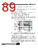
89 / 143 page 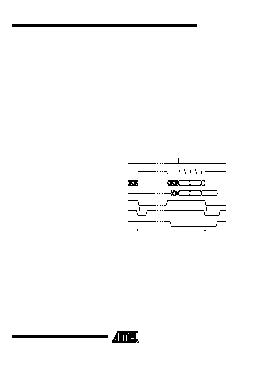 89 AT89C51AC3 4383B–8051–01/05 Error Conditions The following flags in the SPSCR register indicate the SPI error conditions: Mode Fault Error (MODF) Mode Fault error in Master mode SPI indicates that the level on the Slave Select (SS) pin is inconsistent with the actual mode of the device. • Mode fault detection in Master mode: MODF is set to warn that there may be a multi-master conflict for system control. In this case, the SPI system is affected in the following ways: – An SPI receiver/error CPU interrupt request is generated – The SPEN bit in SPCON is cleared. This disables the SPI – The MSTR bit in SPCON is cleared Clearing the MODF bit is accomplished by a read of SPSCR register with MODF bit set, followed by a write to the SPCON register. SPEN Control bit may be restored to its orig- inal set state after the MODF bit has been cleared. Figure 50. Mode Fault Conditions in Master Mode (Cpha =’1’/Cpol =’0’) Note: When SS is discarded (SS disabled) it is not possible to detect a MODF error in master mode because the SPI is internally unselected and the SS pin is a general purpose I/O. • Mode fault detection in Slave mode In slave mode, the MODF error is detected when SS goes high during a transmission. A transmission begins when SS goes low and ends once the incoming SCK goes back to its idle level following the shift of the eighteen data bit. A MODF error occurs if a slave is selected (SS is low) and later unselected (SS is high) even if no SCK is sent to that slave. At any time, a ’1’ on the SS pin of a slave SPI puts the MISO pin in a high impedance state and internal state counter is cleared. Also, the slave SPI ignores all incoming SCK clocks, even if it was already in the middle of a transmission. A new transmission will be performed as soon as SS pin returns low. SCK SS (master) 1 2 3 SCK cycle # 0 0 SS (slave) (from master) MODF detected B6 MSB B6 MSB 0 z 1 0 z 1 0 z 1 0 z 1 0 z 1 0 0 z 1 SPI enable MODF detected MOSI MISO (from master) (from slave) B5 |
|
Link URL |
| Does ALLDATASHEET help your business so far? [ DONATE ] |
About Alldatasheet | Advertisement | Contact us | Privacy Policy | Link to Datasheet | Link Exchange | Manufacturer List All Rights Reserved©Alldatasheet.com |
| Russian : Alldatasheetru.com | Korean : Alldatasheet.co.kr | Spanish : Alldatasheet.es | French : Alldatasheet.fr | Italian : Alldatasheetit.com Portuguese : Alldatasheetpt.com | Polish : Alldatasheet.pl | Vietnamese : Alldatasheet.vn Indian : Alldatasheet.in | Mexican : Alldatasheet.com.mx | British : Alldatasheet.co.uk | New Zealand : Alldatasheet.co.nz |
|
Family Site : ic2ic.com |
icmetro.com |
 New Zealand ▼
 English
 Chinese
 German
 Japanese
 Russian
 Korean
 Spanish
 French
 Italian
 Portuguese
 Polish
 Vietnamese
 Indian
 Mexican
 British
 New Zealand