 |
Electronic Components Datasheet Search |
|
|
Electronic Components Datasheet Search |
|
UPD75P218KB Datasheet(PDF) 21 Page - NEC |
|
|
|||||||||||||||||||||||||||||
UPD75P218KB Datasheet(HTML) 21 Page - NEC |
|
|
21 / 36 page 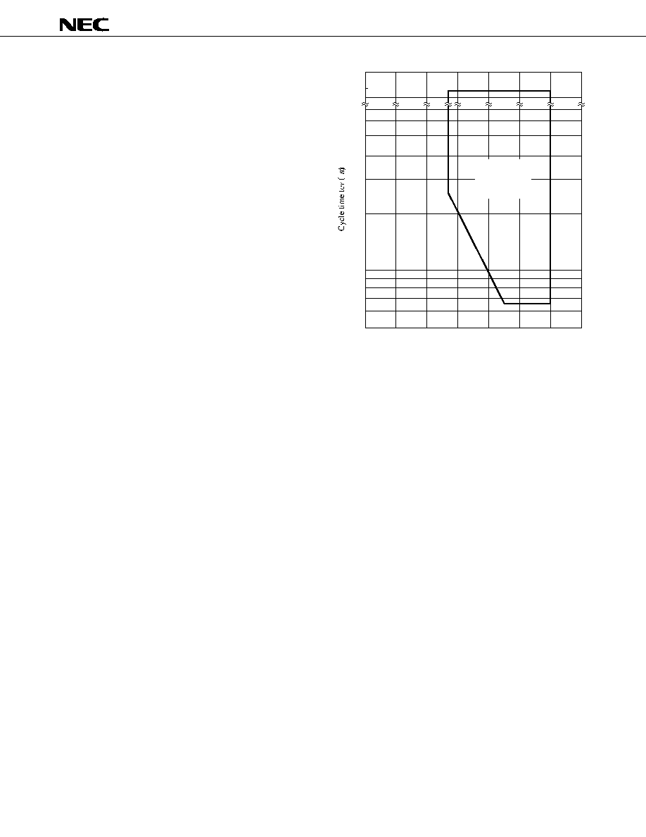 21 µPD75P218 Notes 1. The CPU clock ( Φ) cycle time is deter- mined by the oscillator frequency of the connected resonator, the system clock control register (SCC), and the processor clock control register (PCC). The right chart shows the cycle time tCY characteristics for power supply voltage VDD during the main system clock opera- tion. 2. 2tCY or 128/fXX, depending on the setting of the interrupt mode register (IM0). Guaranteed operating range 02 3 4 5 6 1 (Main system clock) 0.5 1 2 3 4 5 6 30 32 40 tCY VDD vs Power supply voltage VDD (V) |
|
Link URL |
| Does ALLDATASHEET help your business so far? [ DONATE ] |
About Alldatasheet | Advertisement | Contact us | Privacy Policy | Link to Datasheet | Link Exchange | Manufacturer List All Rights Reserved©Alldatasheet.com |
| Russian : Alldatasheetru.com | Korean : Alldatasheet.co.kr | Spanish : Alldatasheet.es | French : Alldatasheet.fr | Italian : Alldatasheetit.com Portuguese : Alldatasheetpt.com | Polish : Alldatasheet.pl | Vietnamese : Alldatasheet.vn Indian : Alldatasheet.in | Mexican : Alldatasheet.com.mx | British : Alldatasheet.co.uk | New Zealand : Alldatasheet.co.nz |
|
Family Site : ic2ic.com |
icmetro.com |
 New Zealand ▼
 English
 Chinese
 German
 Japanese
 Russian
 Korean
 Spanish
 French
 Italian
 Portuguese
 Polish
 Vietnamese
 Indian
 Mexican
 British
 New Zealand


