|
Electronic Components Datasheet Search |
|
|
Electronic Components Datasheet Search |
|
PWR-2700-DC-R Datasheet(PDF) 23 Page - Arista Networks, Inc |
|
|
|||||||||||||||||||||||||||||
PWR-2700-DC-R Datasheet(HTML) 23 Page - Arista Networks, Inc |
|
|
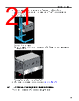
23 / 80 page  Rack Mounting the Switch Table 6: Cage Nut Locations on Rack Switch Cage Nut Locations 7512N (Front of the rack) Top hole 1st U Middle hole 2nd U Middle hole 4th U Bottom hole 5th U Top hole 9th U Middle hole 15th U Middle hole 17th U 7516N (Front of the rack) Top hole 1st U Middle hole 2nd U Middle hole 4th U Bottom hole 5th U Top hole 13th U Top hole 16th U Bottom hole 26th U Top hole 28th U 7512N and 7516N (Rear of the rack) Top hole 1st U Middle hole 2nd U Middle hole 4th U Bottom hole 5th U 2. Attach the front bracket of the shelf support to the left front rack post, as shown in Figure 13: Left Front Post Assembly. An up arrow is printed on the shelf support to indicate its proper orientation. Unthreaded rack holes: Use the M6 screws and cage nuts supplied in the accessory kit. Threaded rack holes: Attach the front bracket to the post with screws that can be threaded through the rack post. 3. Hook the alignment pin to the bottom hole of the 6th U from bottom as shown. 19 |
|
Link URL |
| Does ALLDATASHEET help your business so far? [ DONATE ] |
About Alldatasheet | Advertisement | Contact us | Privacy Policy | Link to Datasheet | Link Exchange | Manufacturer List All Rights Reserved©Alldatasheet.com |
| Russian : Alldatasheetru.com | Korean : Alldatasheet.co.kr | Spanish : Alldatasheet.es | French : Alldatasheet.fr | Italian : Alldatasheetit.com Portuguese : Alldatasheetpt.com | Polish : Alldatasheet.pl | Vietnamese : Alldatasheet.vn Indian : Alldatasheet.in | Mexican : Alldatasheet.com.mx | British : Alldatasheet.co.uk | New Zealand : Alldatasheet.co.nz |
|
Family Site : ic2ic.com |
icmetro.com |
 New Zealand ▼
 English
 Chinese
 German
 Japanese
 Russian
 Korean
 Spanish
 French
 Italian
 Portuguese
 Polish
 Vietnamese
 Indian
 Mexican
 British
 New Zealand