|
Electronic Components Datasheet Search |
|
|
Electronic Components Datasheet Search |
|
H8/3021 Datasheet(PDF) 410 Page - Renesas Technology Corp |
|
|
|||||||||||||||||||||||||||||
H8/3021 Datasheet(HTML) 410 Page - Renesas Technology Corp |
|
|
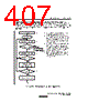
410 / 712 page  11. Serial Communication Interface Rev.2.00 Mar. 22, 2007 Page 386 of 684 REJ09B0352-0200 No Yes No Yes Yes No Yes No Initialize Start transmitting and receiving Read TDRE flag in SSR TDRE = 1? Write transmit data in TDR and clear TDRE flag to 0 in SSR RDRF = 1? Read RDRF flag in SSR Read receive data from RDR and clear RDRF flag to 0 in SSR Read ORER flag in SSR ORER = 1? End of transmitting and receiving? 1 2 5 3 1. 2. 3. 4. 5. SCI initialization: the transmit data output function of the TxD pin and receive data input function of the RxD pin are selected, enabling simultaneous transmitting and receiving. SCI status check and transmit data write: read SSR, check that the TDRE flag is 1, then write transmit data in TDR and clear the TDRE flag to 0. Error handling Note: When switching from transmitting or receiving to simultaneous transmitting and receiving, clear the TE and RE bits both to 0, then set the TE and RE bits both to 1. Clear TE and RE bits to 0 in SCR End Notification that the TDRE flag has changed from 0 to 1 can also be given by the TXI interrupt. Receive error handling: if a receive error occurs, read the ORER flag in SSR, then after executing the neces- sary error handling, clear the ORER flag to 0. Neither transmitting nor receiving can resume while the ORER flag remains set to 1. SCI status check and receive data read: read SSR, check that the RDRF flag is 1, then read receive data from RDR and clear the RDRF flag to 0. Notification that the RDRF flag has changed from 0 to 1 can also be given by the RXI interrupt. To continue transmitting and receiving serial data: check the RDRF flag, read RDR, and clear the RDRF flag to 0 before the MSB (bit 7) of the current frame is received. Also check that the TDRE flag is set to 1, indicat- ing that data can be written, write data in TDR, then clear the TDRE flag to 0 before the MSB (bit 7) of the current frame is transmitted. 4 Figure 11.20 Sample Flowchart for Serial Transmitting |
|
Link URL |
| Does ALLDATASHEET help your business so far? [ DONATE ] |
About Alldatasheet | Advertisement | Contact us | Privacy Policy | Link to Datasheet | Link Exchange | Manufacturer List All Rights Reserved©Alldatasheet.com |
| Russian : Alldatasheetru.com | Korean : Alldatasheet.co.kr | Spanish : Alldatasheet.es | French : Alldatasheet.fr | Italian : Alldatasheetit.com Portuguese : Alldatasheetpt.com | Polish : Alldatasheet.pl | Vietnamese : Alldatasheet.vn Indian : Alldatasheet.in | Mexican : Alldatasheet.com.mx | British : Alldatasheet.co.uk | New Zealand : Alldatasheet.co.nz |
|
Family Site : ic2ic.com |
icmetro.com |
 New Zealand ▼
 English
 Chinese
 German
 Japanese
 Russian
 Korean
 Spanish
 French
 Italian
 Portuguese
 Polish
 Vietnamese
 Indian
 Mexican
 British
 New Zealand