|
Electronic Components Datasheet Search |
|
|
Electronic Components Datasheet Search |
|
A8603KESTR-R Datasheet(PDF) 23 Page - Allegro MicroSystems |
|
|
|||||||||||||||||||||||||||||
A8603KESTR-R Datasheet(HTML) 23 Page - Allegro MicroSystems |
|
|
23 / 42 page 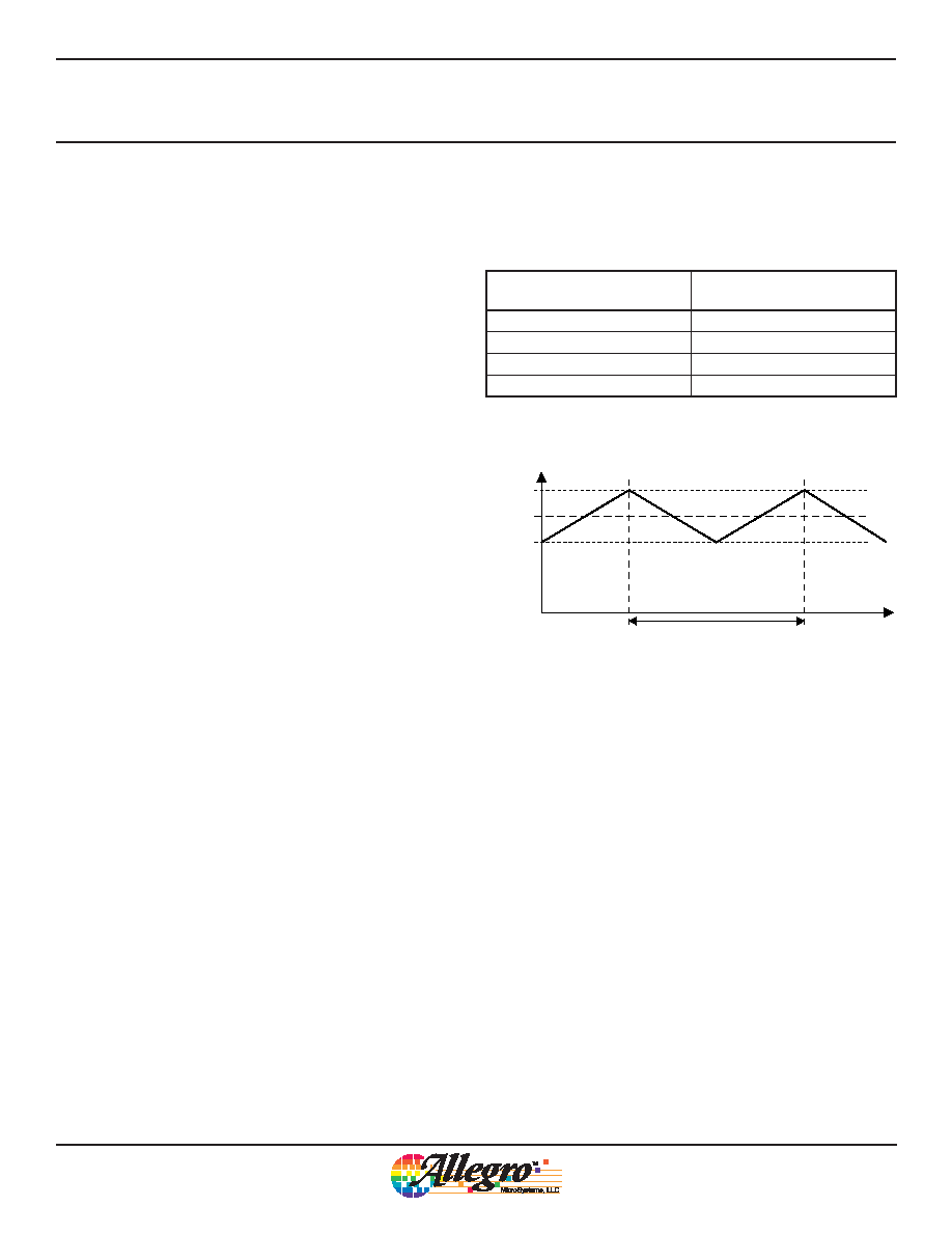 Multiple-Output Regulator for Automotive LCD Displays A8603 23 Allegro MicroSystems, LLC 115 Northeast Cutoff Worcester, Massachusetts 01615-0036 U.S.A. 1.508.853.5000; www.allegromicro.com Boost Frequency Dithering The A8603 has an optional dithering function for the boost switching frequency. When enabled, the switching frequency is varied linearly within a certain frequency range, as modulated by a triangular ramp signal. By spreading the frequency of the boost converter, the overall system noise magnitude can be greatly reduced. Note that the frequency dithering function is not avail- able when an external synchronization signal is used at the FSET pin. The dithering feature is controlled by Register 0x10. Frequency of the dithering modulation ramp signal is 12 kHz typical. Table 15: Register 0x10 Dithering Feature Reg0x10 Content (in binary) Dithering Feature (frequency range) ‘00’ 0% ‘01’ ±5% ‘10’ ±10% ‘11’ ±15% Frequency Time f SW ~80 µs 2.2 MHz 2.0 MHz 1.8 MHz Figure 11: Switching Frequency Varied Linearly In this example, Reg0x10 = ‘10’ and the central switching frequency is fSW = 2.0 MHz. The actual frequency is varied linearly between fSW –10% and fSW +10% by the modulating frequency at 12 kHz. |
|
Link URL |
| Does ALLDATASHEET help your business so far? [ DONATE ] |
About Alldatasheet | Advertisement | Contact us | Privacy Policy | Link to Datasheet | Link Exchange | Manufacturer List All Rights Reserved©Alldatasheet.com |
| Russian : Alldatasheetru.com | Korean : Alldatasheet.co.kr | Spanish : Alldatasheet.es | French : Alldatasheet.fr | Italian : Alldatasheetit.com Portuguese : Alldatasheetpt.com | Polish : Alldatasheet.pl | Vietnamese : Alldatasheet.vn Indian : Alldatasheet.in | Mexican : Alldatasheet.com.mx | British : Alldatasheet.co.uk | New Zealand : Alldatasheet.co.nz |
|
Family Site : ic2ic.com |
icmetro.com |
 New Zealand ▼
 English
 Chinese
 German
 Japanese
 Russian
 Korean
 Spanish
 French
 Italian
 Portuguese
 Polish
 Vietnamese
 Indian
 Mexican
 British
 New Zealand