 |
Electronic Components Datasheet Search |
|
|
Electronic Components Datasheet Search |
|
STLED524 Datasheet(PDF) 68 Page - STMicroelectronics |
|
|
|||||||||||||||||||||||||||||
STLED524 Datasheet(HTML) 68 Page - STMicroelectronics |
|
|
68 / 72 page 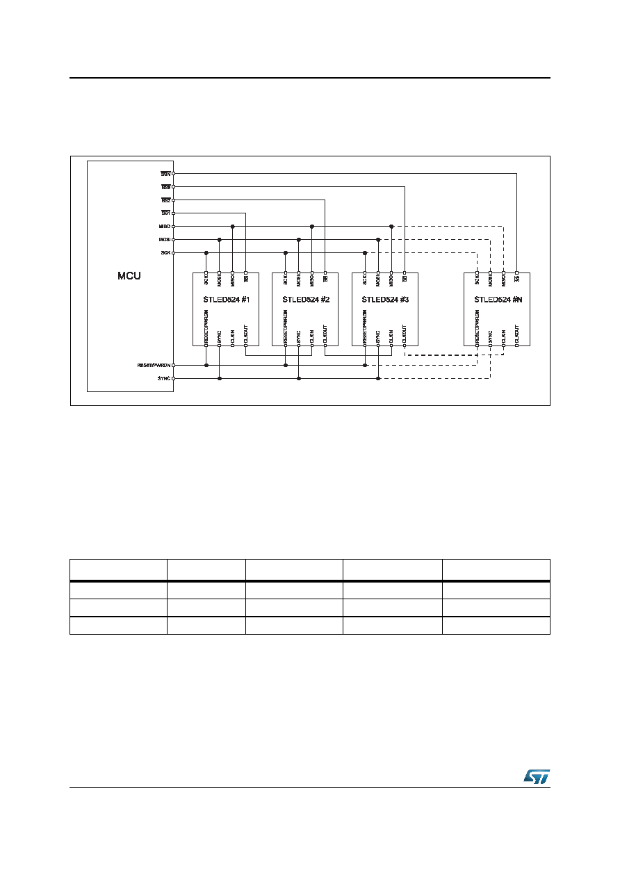 Application information STLED524 68/72 DocID026217 Rev 1 6.3 Multiple devices in cascade The STLED524 multiple devices can be linked in cascade according to Figure 30. Figure 30. STLED524 cascade • Each device in cascade needs a controlled SS input separately. • RESET/PWRDN, SYNC, SCK, MISO and MOSI pins are connected in parallel. • CLKOUT of nth device is connected to CLKIN of the (n+1)th device. • CLKIN of the 1st device does not have to be connected, if internal clock of the 1st device is used to provide clock for the whole cascade. • Another possibility for CLOCK signal is to connect all CLKIN pins to an external clock. 6.3.1 Register setup for the STLED524 cascade Position means position of the device in cascade: CLKIN bit of the first device is set to 0, because the first device uses its internal clock. CLKOUT bit of the last device is set to 0, because there is no other device connected. SYNCEN bit of all devices has to be set to 1. SYNCSEL bit can be either 0 or 1, but the value has to be the same as all devices in cascade. GIPG2103141214LM Table 71. Cascade register setup Position CLKIN CLKOUT SYNCEN SYNCSEL 10 1 1 X 2 to (n-1) 1 1 1 X n1 0 1 X |
|
Link URL |
| Does ALLDATASHEET help your business so far? [ DONATE ] |
About Alldatasheet | Advertisement | Contact us | Privacy Policy | Link to Datasheet | Link Exchange | Manufacturer List All Rights Reserved©Alldatasheet.com |
| Russian : Alldatasheetru.com | Korean : Alldatasheet.co.kr | Spanish : Alldatasheet.es | French : Alldatasheet.fr | Italian : Alldatasheetit.com Portuguese : Alldatasheetpt.com | Polish : Alldatasheet.pl | Vietnamese : Alldatasheet.vn Indian : Alldatasheet.in | Mexican : Alldatasheet.com.mx | British : Alldatasheet.co.uk | New Zealand : Alldatasheet.co.nz |
|
Family Site : ic2ic.com |
icmetro.com |
 New Zealand ▼
 English
 Chinese
 German
 Japanese
 Russian
 Korean
 Spanish
 French
 Italian
 Portuguese
 Polish
 Vietnamese
 Indian
 Mexican
 British
 New Zealand


