 |
Electronic Components Datasheet Search |
|
|
Electronic Components Datasheet Search |
|
STLED524 Datasheet(PDF) 15 Page - STMicroelectronics |
|
|
|||||||||||||||||||||||||||||
STLED524 Datasheet(HTML) 15 Page - STMicroelectronics |
|
|
15 / 72 page 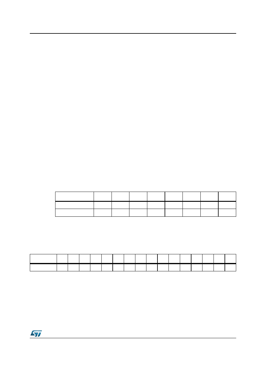 DocID026217 Rev 1 15/72 STLED524 Detailed description 4 Detailed description The STLED524 is a 5x24 LED dot matrix display driver. It includes 24 low-side current mirrors (for each LED in a row). Rows are multiplexed by 5 internal PMOS transistors. Current mirrors are supplied by the integrated boost converter. Its output voltage is adjustable so it can be adapted to the forward voltage of LEDs. It reduces power dissipation and improves efficiency. 4.1 Boost converter The step-up bridge with current mode control regulation provides output voltage according to the value of VOUT[3:0] register. This voltage should be adjusted to be high enough to provide sufficient headroom to regulate current sources connected to COL 0-23 pins. On the other hand, keeping boost output voltage unnecessarily high, increases power dissipation and degrades efficiency. Boost incorporates a zero current comparator. When the input voltage is close to the output voltage, pulse-skipping is applied to keep the output voltage regulated. If the input voltage is higher than desired output voltage, boost switches to bypass mode automatically. In this mode, the output voltage is equal to the input voltage lowered by voltage drop on the PMOS transistor. Boost converter is enabled only when BSTEN bit in the boost control register is set to 1. VOUT setting shouldn’t be changed when boost is on (BSTEN=1). BSTEN = 0, boost is disabled BSTEN = 1, boost is enabled One step = 120 mV Table 7. Boost control register bits Boost control Bit 7 Bit 6 Bit 5 Bit 4 Bit 3 Bit 2 Bit 1 Bit 0 Add = 16h BSTEN - - - VOUT3 VOUT2 VOUT1 VOUT0 Default 000 0101 0 Table 8. Boost output voltage VOUT[3:0] 0001 0203040506 0708 09 0A 0B 0C 0D 0E 0F VOUT[V] 2.80 2.92 3.04 3.16 3.28 3.40 3.52 3.64 3.76 3.88 4.00 4.12 4.24 4.36 4.48 4.60 |
|
Link URL |
| Does ALLDATASHEET help your business so far? [ DONATE ] |
About Alldatasheet | Advertisement | Contact us | Privacy Policy | Link to Datasheet | Link Exchange | Manufacturer List All Rights Reserved©Alldatasheet.com |
| Russian : Alldatasheetru.com | Korean : Alldatasheet.co.kr | Spanish : Alldatasheet.es | French : Alldatasheet.fr | Italian : Alldatasheetit.com Portuguese : Alldatasheetpt.com | Polish : Alldatasheet.pl | Vietnamese : Alldatasheet.vn Indian : Alldatasheet.in | Mexican : Alldatasheet.com.mx | British : Alldatasheet.co.uk | New Zealand : Alldatasheet.co.nz |
|
Family Site : ic2ic.com |
icmetro.com |
 New Zealand ▼
 English
 Chinese
 German
 Japanese
 Russian
 Korean
 Spanish
 French
 Italian
 Portuguese
 Polish
 Vietnamese
 Indian
 Mexican
 British
 New Zealand


