|
Electronic Components Datasheet Search |
|
|
Electronic Components Datasheet Search |
|
STPW12 Datasheet(PDF) 12 Page - STMicroelectronics |
|
|
|||||||||||||||||||||||||||||
STPW12 Datasheet(HTML) 12 Page - STMicroelectronics |
|
|
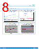
12 / 23 page  Figure 18. Monitor signal vs. power Ch1 1V/div Ch2 1V/div Ch3 1V/div Ch4 1A/div 100µs/div 3 M1 4 2 M1 15W 1 Power Monitor Output voltage Input voltage Output Current Figure 19. Monitor signal vs. power (zoom) ts tf Power Monitor Output voltage Input voltage Table 5. Monitor signal truth table Device status Mon / fault Normal operation IMON Power limit triggered High (for 10 μs) Thermal shutdown Low Off-state Low Current limit triggered High The voltage at high logic level is typically 4.5 V, therefore the pin can be directly interfaced to a 5 V compliant microcontroller or ADC device. 7.4 Auto-retry delay time setting The auto-retry delay time, defined as the time between a power interruption event and the device restart, can be set by choosing the appropriate value for the CS capacitor, according to the graph in Figure 16. Auto-retry delay time vs. CS. 7.5 PWM mode description, masking time In this mode the device internal power switch can be driven on/off by an external PWM signal, provided to the PWM pin (square wave, maximum 2 kHz, duty cycle 20% - 100%). It is important to notice that in this mode the power limit protection is kept inactive for a delay time (masking time) selected by an external RD resistor (see Table 6. Masking time vs. RD), so to avoid false triggering during in-rush power events at each PWM signal rising edge. Eleven discrete steps are available for the PWM masking time. They can be selected by choosing an appropriate value of the RD resistor, as shown in the following table, where the standard 1% resistors are used. For a correct operation of the device, the RDelay pin must not be directly connected to GND, and the minimum masking time (45 µs) is achieved by using RD = 1 kΩ. The masking time is measured starting from when the PWM rising edge overcomes the VSPH threshold till the monitor signal starts increasing (see Figure 7. Masking time, fault signal). PWM masking time is active also during each start-up cycle (including auto-retry), in order to avoid that inrush current flowing to the output capacitor triggers the power limit, which would cause a premature shutdown. STPW12 Auto-retry delay time setting DS12478 - Rev 1 page 12/23 |
|
|
Link URL |
| Does ALLDATASHEET help your business so far? [ DONATE ] |
About Alldatasheet | Advertisement | Contact us | Privacy Policy | Link to Datasheet | Link Exchange | Manufacturer List All Rights Reserved©Alldatasheet.com |
| Russian : Alldatasheetru.com | Korean : Alldatasheet.co.kr | Spanish : Alldatasheet.es | French : Alldatasheet.fr | Italian : Alldatasheetit.com Portuguese : Alldatasheetpt.com | Polish : Alldatasheet.pl | Vietnamese : Alldatasheet.vn Indian : Alldatasheet.in | Mexican : Alldatasheet.com.mx | British : Alldatasheet.co.uk | New Zealand : Alldatasheet.co.nz |
|
Family Site : ic2ic.com |
icmetro.com |
 New Zealand ▼
 English
 Chinese
 German
 Japanese
 Russian
 Korean
 Spanish
 French
 Italian
 Portuguese
 Polish
 Vietnamese
 Indian
 Mexican
 British
 New Zealand