|
Electronic Components Datasheet Search |
|
|
Electronic Components Datasheet Search |
|
FAN-7002-R Datasheet(PDF) 23 Page - Arista Networks, Inc |
|
|
|||||||||||||||||||||||||||||
FAN-7002-R Datasheet(HTML) 23 Page - Arista Networks, Inc |
|
|
23 / 66 page 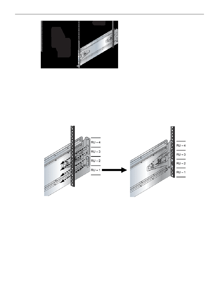 Rack Mounting the Switch Figure 11: Adjusting the Right Shelf 1 Front left rack post 2 Front right rack post 3 Rear right rack post 5. Attach the back-side of the shelf into the rear shelf by gliding the slide-end such that the rack plugs (if present) and guide pins are inserted into the rack post holes (Figure 12: Seating the Left Shelf). The bottom rack plug must be inserted one RU (three rack holes) above the bottom rack plug on the front side of the shelf. If the locking mechanism and plugs are not used, fasten the back-side of the shelf to the rear shelf, and skip to Step 6. Figure 12: Seating the Left Shelf 6. Close the rear locking mechanism latch if present (Figure 7: Right Shelf – Outer View). 3.2.3.2 Mounting Ear Installation The mounting ears attach the top of the switch to the rack posts. Their placement on the posts depend on the switch model (Component Placement). The installation process for each mounting ear is identical. The inner side of the mounting ear (which includes the locking mechanism latch) is oriented between the front rack posts. Depending on the rack kit configuration, a locking mechanism may not be present. In the following section, all illustrations feature the right mounting ear. Perform the following procedure for each mounting ear: 19 |
|
Link URL |
| Does ALLDATASHEET help your business so far? [ DONATE ] |
About Alldatasheet | Advertisement | Contact us | Privacy Policy | Link to Datasheet | Link Exchange | Manufacturer List All Rights Reserved©Alldatasheet.com |
| Russian : Alldatasheetru.com | Korean : Alldatasheet.co.kr | Spanish : Alldatasheet.es | French : Alldatasheet.fr | Italian : Alldatasheetit.com Portuguese : Alldatasheetpt.com | Polish : Alldatasheet.pl | Vietnamese : Alldatasheet.vn Indian : Alldatasheet.in | Mexican : Alldatasheet.com.mx | British : Alldatasheet.co.uk | New Zealand : Alldatasheet.co.nz |
|
Family Site : ic2ic.com |
icmetro.com |
 New Zealand ▼
 English
 Chinese
 German
 Japanese
 Russian
 Korean
 Spanish
 French
 Italian
 Portuguese
 Polish
 Vietnamese
 Indian
 Mexican
 British
 New Zealand