|
Electronic Components Datasheet Search |
|
|
Electronic Components Datasheet Search |
|
AT89C51ID2-RDTIM Datasheet(PDF) 19 Page - ATMEL Corporation |
|
|
|||||||||||||||||||||||||||||
AT89C51ID2-RDTIM Datasheet(HTML) 19 Page - ATMEL Corporation |
|
|
19 / 159 page 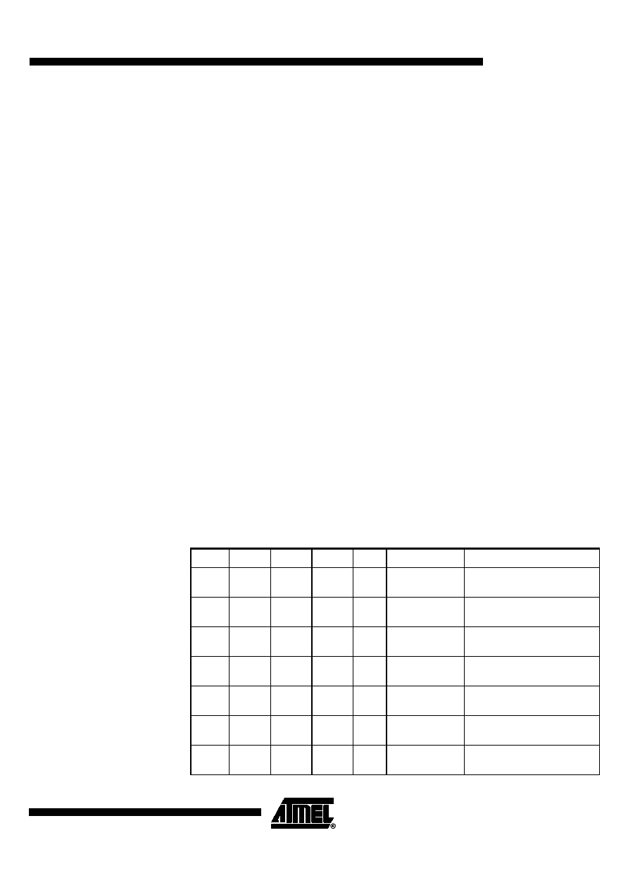 19 AT89C51ID2 4289A–8051–09/03 • It is always possible to switch dynamically by software from OscA to OscB, and vice versa by changing CKS bit. Idle Modes • IDLE modes are achieved by using any instruction that writes into PCON.0 bit (IDL) • IDLE modes A and B depend on previous software sequence, prior to writing into PCON.0 bit: • IDLE MODE A: OscA is running (OscAEn = 1) and selected (CKS = 1) • IDLE MODE B: OscB is running (OscBEn = 1) and selected (CKS = 0) • The unused oscillator OscA or OscB can be stopped by software by clearing OscAEn or OscBEn respectively. • IDLE mode can be canceled either by Reset, or by activation of any enabled interruption • In both cases, PCON.0 bit (IDL) is cleared by hardware • Exit from IDLE modes will leave Oscillators control bits (OscEnA, OscEnB, CKS) unchanged. Power Down Modes • POWER DOWN modes are achieved by using any instruction that writes into PCON.1 bit (PD) • POWER DOWN modes A and B depend on previous software sequence, prior to writing into PCON.1 bit: • Both OscA and OscB will be stopped. • POWER DOWN mode can be cancelled either by a hardware Reset, an external interruption, or the keyboard interrupt. • By Reset signal: The CPU will restart according to OSC bit in Hardware Security Bit (HSB) register. • By INT0 or INT1 interruption, if enabled: (standard behavioral), request on Pads must be driven low enough to ensure correct restart of the oscillator which was selected when entering in Power down. • By keyboard Interrupt if enabled: a hardware clear of the PCON.1 flag ensure the restart of the oscillator which was selected when entering in Power down. Table 19. Overview PCON.1 PCON.0 OscBEn OscAEn CKS Selected Mode Comment 00 0 1 1 NORMAL MODE A, OscB stopped Default mode after power-up or Warm Reset 00 1 1 1 NORMAL MODE A, OscB running Default mode after power-up or Warm Reset + OscB running 00 1 0 0 NORMAL MODE B, OscA stopped OscB running and selected 00 1 1 0 NORMAL MODE B, OscA running OscB running and selected + OscA running XX 0 0 X INVALID OscA & OscB cannot be stopped at the same time XX X 0 1 INVALID OscA must not be stopped, as used for CPU and peripherals XX 0 X 0 INVALID OscB must not be stopped as used for CPU and peripherals |
|
Link URL |
| Does ALLDATASHEET help your business so far? [ DONATE ] |
About Alldatasheet | Advertisement | Contact us | Privacy Policy | Link to Datasheet | Link Exchange | Manufacturer List All Rights Reserved©Alldatasheet.com |
| Russian : Alldatasheetru.com | Korean : Alldatasheet.co.kr | Spanish : Alldatasheet.es | French : Alldatasheet.fr | Italian : Alldatasheetit.com Portuguese : Alldatasheetpt.com | Polish : Alldatasheet.pl | Vietnamese : Alldatasheet.vn Indian : Alldatasheet.in | Mexican : Alldatasheet.com.mx | British : Alldatasheet.co.uk | New Zealand : Alldatasheet.co.nz |
|
Family Site : ic2ic.com |
icmetro.com |
 New Zealand ▼
 English
 Chinese
 German
 Japanese
 Russian
 Korean
 Spanish
 French
 Italian
 Portuguese
 Polish
 Vietnamese
 Indian
 Mexican
 British
 New Zealand