|
Electronic Components Datasheet Search |
|
|
Electronic Components Datasheet Search |
|
T89C51AC2-RLSI-M Datasheet(PDF) 16 Page - ATMEL Corporation |
|
|
|||||||||||||||||||||||||||||
T89C51AC2-RLSI-M Datasheet(HTML) 16 Page - ATMEL Corporation |
|
|
16 / 117 page 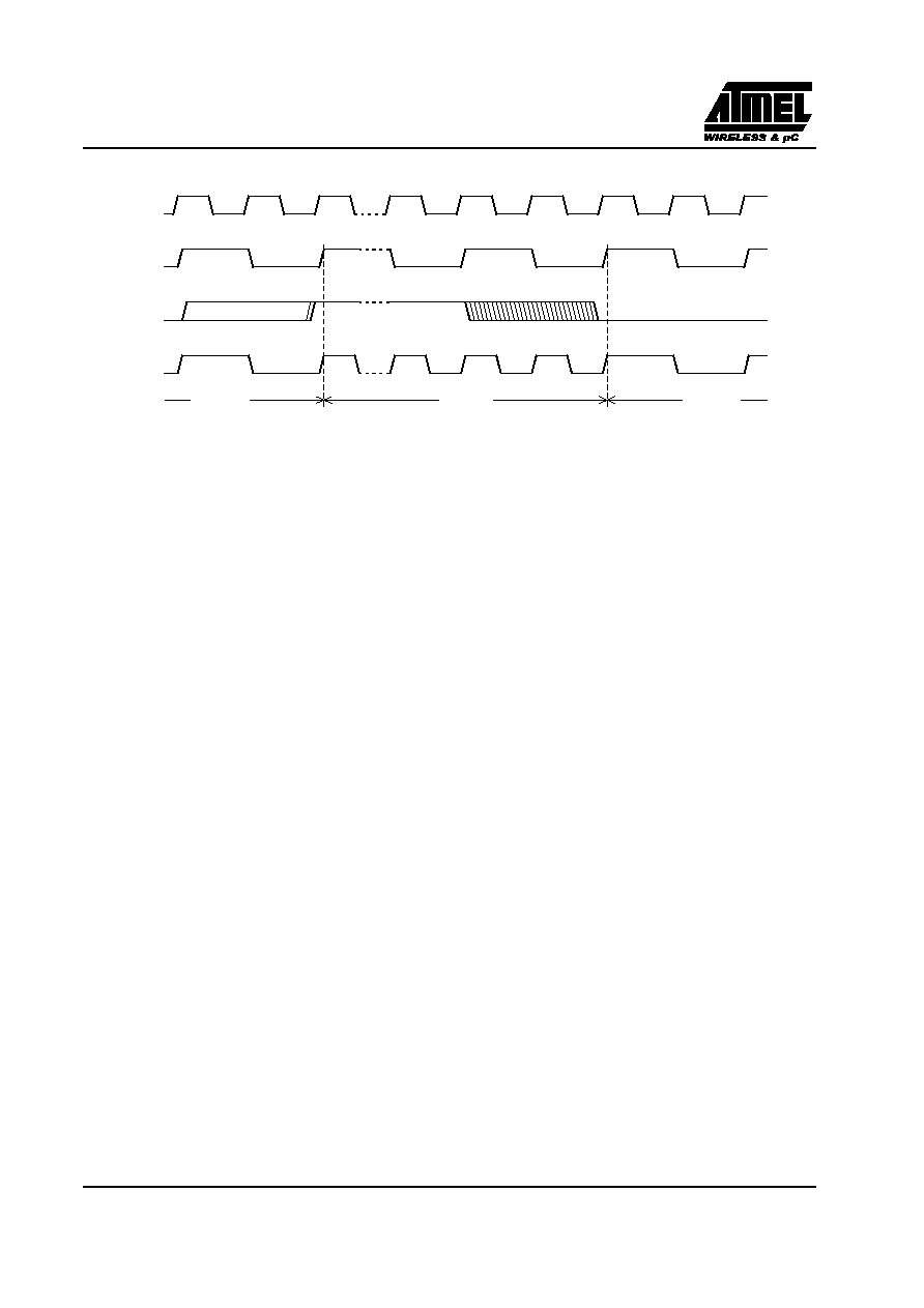 16 Draft.A - March 30, 2001 Preview - Confidential T89C51AC2 Figure 6. Mode Switching Waveforms The X2 bit in the CKCON register (See Table 7) allows switching from 12 clock cycles per instruction to 6 clock cycles and vice versa. At reset, the standard speed is activated (STD mode). Setting this bit activates the X2 feature (X2 mode). CAUTION In order to prevent any incorrect operation while operating in the X2 mode, users must be aware that all peripherals using the clock frequency as a time reference (UART, timers...) will have their time reference divided by two. For example a free running timer generating an interrupt every 20 ms will then generate an interrupt every 10 ms. A UART with a 4800 baud rate will have a 9600 baud rate. XTAL2 XTAL1 CPU clock X2 bit X2 Mode STD Mode STD Mode |
|
Link URL |
| Does ALLDATASHEET help your business so far? [ DONATE ] |
About Alldatasheet | Advertisement | Contact us | Privacy Policy | Link to Datasheet | Link Exchange | Manufacturer List All Rights Reserved©Alldatasheet.com |
| Russian : Alldatasheetru.com | Korean : Alldatasheet.co.kr | Spanish : Alldatasheet.es | French : Alldatasheet.fr | Italian : Alldatasheetit.com Portuguese : Alldatasheetpt.com | Polish : Alldatasheet.pl | Vietnamese : Alldatasheet.vn Indian : Alldatasheet.in | Mexican : Alldatasheet.com.mx | British : Alldatasheet.co.uk | New Zealand : Alldatasheet.co.nz |
|
Family Site : ic2ic.com |
icmetro.com |
 New Zealand ▼
 English
 Chinese
 German
 Japanese
 Russian
 Korean
 Spanish
 French
 Italian
 Portuguese
 Polish
 Vietnamese
 Indian
 Mexican
 British
 New Zealand