 |
Electronic Components Datasheet Search |
|
|
Electronic Components Datasheet Search |
|
WM8946ECS/R Datasheet(PDF) 96 Page - Wolfson Microelectronics plc |
|
|
|||||||||||||||||||||||||||||
WM8946ECS/R Datasheet(HTML) 96 Page - Wolfson Microelectronics plc |
|
|
96 / 175 page 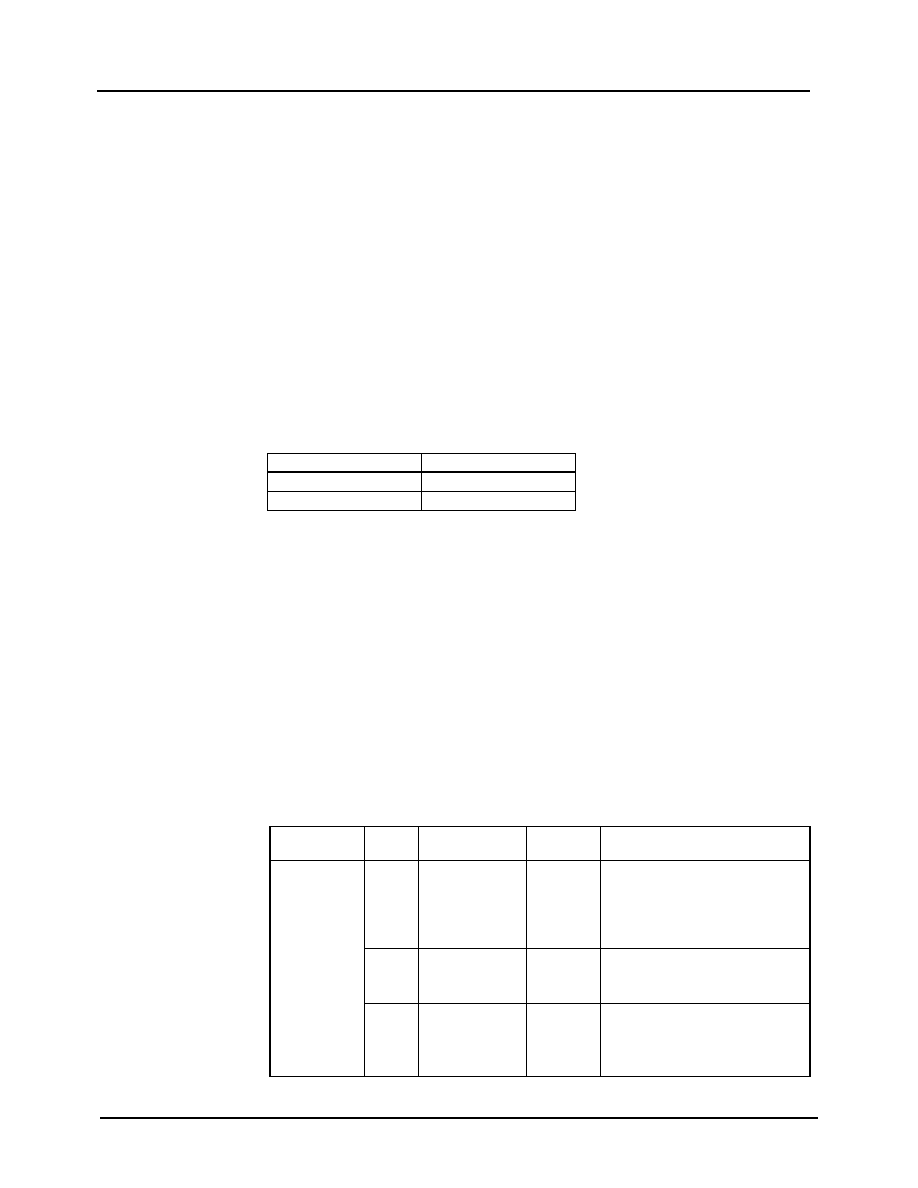 WM8946 Production Data w PD, July 2012, Rev 4.3 96 CONTROL INTERFACE The WM8946 is controlled by writing to its control registers. Readback is available for all registers. The Control Interface can operate as either a 2-, 3- or 4-wire interface: 2-wire (I2C) mode uses pins SCLK and SDA 3-wire (SPI) mode uses pins CS ¯¯ , SCLK and SDA 4-wire (SPI) mode uses pins CS ¯¯ , SCLK, SDA and SDOUT Readback is provided on the bi-directional pin SDA in 2-/3-wire modes. The device address in 2-wire (I2C) mode is 34h. The WM8946 uses 15-bit register addresses and 16-bit data in all Control Interface modes. SELECTION OF CONTROL INTERFACE MODE The WM8946 Control Interface can be configured for I2C mode or SPI modes using the CIFMODE/GPIO3 pin at power-up. The mode selection is as described in Table 63. CIFMODE/GPIO3 INTERFACE FORMAT Low 2 wire High 3- or 4- wire Table 62 Control Interface Mode Selection After the Control Interface Mode has been configured, the MODE_GPIO register bit should be set in order to latch the selection and to allow GPIO functions to be supported on the CIFMODE/GPIO3 pin. After the MODE_GPIO register bit has been set, the Control Interface mode selection will remain latched until a Software Reset or Power On Reset occurs. See “General Purpose Input / Output” for details. In 2-wire (I2C) Control Interface mode, Auto-Increment mode may be selected. This enables multiple write and multiple read operations to be scheduled faster than is possible with single register operations. The auto-increment option is enabled when the AUTO_INC register bit is set. This bit is defined in Table 63. Auto-increment is disabled by default. In SPI modes, 3-wire or 4-wire operation may be selected using the SPI_4WIRE register bit. In 3-wire mode, register readback is provided using the bi-directional pin SDA. In 4-wire mode, register readback is provided using SDOUT. The SDOUT pin may be configured as CMOS or as Open Drain using the SPI_OD bit. In 3-wire mode the SDA pin may be configured as CMOS or as Open Drain using the SPI_OD bit. If the open drain option is selected (SPI_OD = 1) then an external pull-up resistor is required on the SDOUT or SDA output pin. The Control Interface configuration bits are described in Table 63. REGISTER ADDRESS BIT LABEL DEFAULT DESCRIPTION t(14h) Control Interface 2 SPI_OD 0 SDOUT pin configuration (applies to 3-wire and 4-wire mode only) 0 = SDOUT output is CMOS 1 = SDOUT output is open drain 1 SPI_4WIRE 1 SPI control mode select 0 = 3-wire using bidirectional SDA 1 = 4-wire using SDOUT 0 AUTO_INC 0 Enables address auto-increment (applies to 2-wire / I2C mode only) 0 = Disabled 1 = Enabled Table 63 Control Interface Configuration |
|
Link URL |
| Does ALLDATASHEET help your business so far? [ DONATE ] |
About Alldatasheet | Advertisement | Contact us | Privacy Policy | Link to Datasheet | Link Exchange | Manufacturer List All Rights Reserved©Alldatasheet.com |
| Russian : Alldatasheetru.com | Korean : Alldatasheet.co.kr | Spanish : Alldatasheet.es | French : Alldatasheet.fr | Italian : Alldatasheetit.com Portuguese : Alldatasheetpt.com | Polish : Alldatasheet.pl | Vietnamese : Alldatasheet.vn Indian : Alldatasheet.in | Mexican : Alldatasheet.com.mx | British : Alldatasheet.co.uk | New Zealand : Alldatasheet.co.nz |
|
Family Site : ic2ic.com |
icmetro.com |
 New Zealand ▼
 English
 Chinese
 German
 Japanese
 Russian
 Korean
 Spanish
 French
 Italian
 Portuguese
 Polish
 Vietnamese
 Indian
 Mexican
 British
 New Zealand


