 |
Electronic Components Datasheet Search |
|
|
Electronic Components Datasheet Search |
|
The question interval is too short.
Please try again in a few seconds.

Hello, Please ask a question about AX88180 Datasheet
# Example questions:
➢ Describe the role of the gpio0 pin during the chip's reset stage, and how its connection (or lack thereof) determines the data bus width.
➢ What are the voltage requirements for vcc33 and vcc25, and how many pins are dedicated to each?
➢ What are the primary functions of the test0, test1, test2, and test3 pins, and what should they be connected to for normal operation?
| Part No. | AX88180 |
| Manufacturer | ASIX |
| Size | 482 Kbytes |
| Pages | 47 pages |
| Description | High-Performance Non-PCI 32-bit 10/100/1000M Gigabit Ethernet Controller |






1. Overview & Purpose
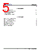
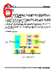
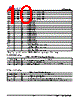
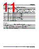
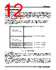
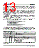
️· Document: This is a portion of a datasheet for the AX88180, likely a network interface controller (NIC) or similar device. It describes the pinout and functionality of the chip.
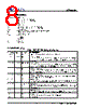
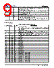
️· Focus: The excerpt details the various pins on the chip, grouping them into categories like Power/Ground, Address/Data, Control, EEPROM Interface, and more. It explains their functions and any special considerations.
2. Key Categories and Pin Functions
️· Power and Ground (Table 6)
- `VCC33`: Multiple pins for 3.3V power supply.
- `VCC25`: Multiple pins for 2.5V power supply.
- `GND`: Multiple ground pins.
️· Host Interface (Data/Address/Control - Table 2)
- `HA1-HA15`: Address bus pins (15 bits).
- `HD1-HD31`: Data bus pins (31 bits). Note the internal pull-down resistors on HD16-HD31, disabled in 32-bit mode.
- `WEN`: Data Write Enable (active low).
- `CSN`: Chip Select Enable (active low).
- `OEN`: Data Output Enable (active low).
️· EEPROM Interface (Table 3)
- `EECLK`: Clock for EEPROM communication.
- `EECS`: Chip Select for EEPROM.
- `EEDI`: Data input to EEPROM.
- `EEDO`: Data output from EEPROM.
️· Regulator Interface (Table 4)
- `VCC33R`: Input for the internal regulator (3.3V).
- `GNDR`: Ground for the internal regulator.
- `REG_EN`: Enable pin for the internal regulator (high to enable, low to disable).
- `V25OUT`: Output from the internal regulator (2.5V, max 250mA).
️· General Purpose I/O (GPIO) (Table 5)
- `GPIO0`: Defines operating mode (16-bit or 32-bit) upon reset. Pull-down resistor sets 32-bit, pull-up sets 16-bit.
- `GPIO1`: Defines endianness (little-endian or big-endian) upon reset. Pull-down sets little-endian, pull-up sets big-endian.
️· Test Pins (Table 2 & 5): These pins are for internal testing and should be connected to ground or appropriate voltage levels during normal operation.
3. Important Notes and Considerations
️· Bit Width Configuration: The `GPIO0` pin determines whether the chip operates in 16-bit or 32-bit mode.
️· Endianness Configuration: The `GPIO1` pin determines the endianness (byte order) - little-endian or big-endian.
️· Pull-Up/Pull-Down Resistors: Several pins have internal pull-up or pull-down resistors, which influence the default state during reset or when the pin is floating.
️· Internal Pull-Down: HD16-HD31 has internal pull-down resistors, these are disabled in 32-bit mode.
️· Power Supply: Ensure proper power supply voltages (3.3V and 2.5V) are provided to the chip.
️· Test Pins: The test pins are for manufacturing testing and not generally used in end products.
4. Summary Table
| Configuration | Pin | Default Value (Floating) |
|---|---|---|
| Bit Width | `GPIO0` | 32-bit (pull-down) |
| Endianness | `GPIO1` | Little-Endian (pull-down) |
1. Overview & Purpose
️· Document: This is a portion of a datasheet for the AX88180, likely a network interface controller (NIC) or similar device. It describes the pinout and functionality of the chip.
️· Focus: The excerpt details the various pins on the chip, grouping them into categories like Power/Ground, Address/Data, Control, EEPROM Interface, and more. It explains their functions and any special considerations.
2. Key Categories and Pin Functions
️· Power and Ground (Table 6)
- `VCC33`: Multiple pins for 3.3V power supply.
- `VCC25`: Multiple pins for 2.5V power supply.
- `GND`: Multiple ground pins.
️· Host Interface (Data/Address/Control - Table 2)
- `HA1-HA15`: Address bus pins (15 bits).
- `HD1-HD31`: Data bus pins (31 bits). Note the internal pull-down resistors on HD16-HD31, disabled in 32-bit mode.
- `WEN`: Data Write Enable (active low).
- `CSN`: Chip Select Enable (active low).
- `OEN`: Data Output Enable (active low).
️· EEPROM Interface (Table 3)
- `EECLK`: Clock for EEPROM communication.
- `EECS`: Chip Select for EEPROM.
- `EEDI`: Data input to EEPROM.
- `EEDO`: Data output from EEPROM.
️· Regulator Interface (Table 4)
- `VCC33R`: Input for the internal regulator (3.3V).
- `GNDR`: Ground for the internal regulator.
- `REG_EN`: Enable pin for the internal regulator (high to enable, low to disable).
- `V25OUT`: Output from the internal regulator (2.5V, max 250mA).
️· General Purpose I/O (GPIO) (Table 5)
- `GPIO0`: Defines operating mode (16-bit or 32-bit) upon reset. Pull-down resistor sets 32-bit, pull-up sets 16-bit.
- `GPIO1`: Defines endianness (little-endian or big-endian) upon reset. Pull-down sets little-endian, pull-up sets big-endian.
️· Test Pins (Table 2 & 5): These pins are for internal testing and should be connected to ground or appropriate voltage levels during normal operation.
3. Important Notes and Considerations
️· Bit Width Configuration: The `GPIO0` pin determines whether the chip operates in 16-bit or 32-bit mode.
️· Endianness Configuration: The `GPIO1` pin determines the endianness (byte order) - little-endian or big-endian.
️· Pull-Up/Pull-Down Resistors: Several pins have internal pull-up or pull-down resistors, which influence the default state during reset or when the pin is floating.
️· Internal Pull-Down: HD16-HD31 has internal pull-down resistors, these are disabled in 32-bit mode.
️· Power Supply: Ensure proper power supply voltages (3.3V and 2.5V) are provided to the chip.
️· Test Pins: The test pins are for manufacturing testing and not generally used in end products.
4. Summary Table
| Configuration | Pin | Default Value (Floating) |
|---|---|---|
| Bit Width | `GPIO0` | 32-bit (pull-down) |
| Endianness | `GPIO1` | Little-Endian (pull-down) |
| Part No. | AX88180 |
| Manufacturer | ASIX |
| Size | 482 Kbytes |
| Pages | 47 pages |
| Description | High-Performance Non-PCI 32-bit 10/100/1000M Gigabit Ethernet Controller |
| Does ALLDATASHEET help your business so far? [ DONATE ] |
About Alldatasheet | Advertisement | Contact us | Privacy Policy | Link to Datasheet | Link Exchange | Manufacturer List All Rights Reserved©Alldatasheet.com |
| Russian : Alldatasheetru.com | Korean : Alldatasheet.co.kr | Spanish : Alldatasheet.es | French : Alldatasheet.fr | Italian : Alldatasheetit.com Portuguese : Alldatasheetpt.com | Polish : Alldatasheet.pl | Vietnamese : Alldatasheet.vn Indian : Alldatasheet.in | Mexican : Alldatasheet.com.mx | British : Alldatasheet.co.uk | New Zealand : Alldatasheet.co.nz |
|
Family Site : ic2ic.com |
icmetro.com |
 New Zealand ▼
  English
 Chinese
 German
 Japanese
 Russian
 Korean
 Spanish
 French
 Italian
 Portuguese
 Polish
 Vietnamese
 Indian
 Mexican
 British