|
Electronic Components Datasheet Search |
|
|
Electronic Components Datasheet Search |
|
AX88180 Datasheet(PDF) 14 Page - ASIX Electronics Corporation |
|
|
|||||||||||||||||||||||||||||
AX88180 Datasheet(HTML) 14 Page - ASIX Electronics Corporation |
|
|
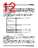
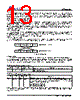
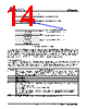
14 / 47 page  AX88180 14 ASIX ELECTRONICS CORPORATION MEMBASE Set MEMBAS6 = 0x0010 TX buffer area (3840 bytes) Registers area (256 bytes) RX buffer area (4096 bytes) Figure 5: 16-bit mode memory mapping The following is an example to indicate how to define a new window base address in 16-bit mode by configuring the MEMBAS6 register. If AX88180 is allocated at the memory base address 0x20_0000 by hardware (i.e. the MEMBASE register is allocated at 0x20_0000) and users would like to set the new window base address to 0x20_1000, the driver should write 0x0010 to the MEMBAS6 register (offset 0x20_0006). In this case, the TX buffer area will be allocated from 0x20_1000 to 0x20_1EFF; the registers area will be allocated from 0x20_1F00 to 0x20_1FFF and the RX buffer area will be allocated from 0x20_2000 to 0x20_2FFF. (Note: AX88180 only decodes low 16-bit address) 3.10 EEPROM Format AX88180 will auto-load data from EEPROM device after hardware reset. If the EEPROM device is not attached, the loading operation will be discarded. The EEPROM mainly provides MAC address information and CIS information if it is used in PCMCIA environment. Below table is the format if EEPROM device is employed. Note: If the MAC address is 12 34 56 78 9A BC (MSB-LSB) then driver should set MACID0=0x9ABC, MACID1=0x5678 and MACID2=0x1234. Address 16-bits data Description 0 Pointer to starting address of CIS area. Set this field to 0x0070 to shorten the download EEPROM if there is no CIS needed. AX88180 only supports the 16-bit mode of 93C56, thus the max value of this field is 0x007F. This field should not be set to 0x0000 or 0xFFFF; otherwise, AX88180 will not recognize the EEPROM during hardware reset. 1 MACID0 data 2 MACID1 data 3 MACID2 data 4 Reserved, keep all 0’s 5 Bit0: When GPIO0 is set to ‘1’ in reset stage, this bit indicates AX88180 whether it is in the environment of PCMCIA. 0 = General 16-bit mode, 1= Special for PCMCIA environment of 16-bit mode. Bit1: must be ‘0’ Bit2: 1 = set RGMII mode by EEPROM, 0 = none. (The setting will be cleared when software resets) Bit3: 1 = set Gigabit mode by EEPROM, 0=none (The setting will be cleared when software resets) Others bits must set to 0s 6 ~ 11 Reserved, keep all 0’s 12 ~ 127 CIS area, if AX88180 is used in PCMCIA system, otherwise set them to all ‘0s’ 15 0 Registers area (xx_1F00 ~ 1FFF) RX buffer area (xx_2000 ~ 2FFF) Base address (xx_0000) New window base address (xx_1000) TX buffer area (xx_1000 ~ 1EFF) Base address + 6 (xx_0006) |
|
Link URL |
| Does ALLDATASHEET help your business so far? [ DONATE ] |
About Alldatasheet | Advertisement | Contact us | Privacy Policy | Link to Datasheet | Link Exchange | Manufacturer List All Rights Reserved©Alldatasheet.com |
| Russian : Alldatasheetru.com | Korean : Alldatasheet.co.kr | Spanish : Alldatasheet.es | French : Alldatasheet.fr | Italian : Alldatasheetit.com Portuguese : Alldatasheetpt.com | Polish : Alldatasheet.pl | Vietnamese : Alldatasheet.vn Indian : Alldatasheet.in | Mexican : Alldatasheet.com.mx | British : Alldatasheet.co.uk | New Zealand : Alldatasheet.co.nz |
|
Family Site : ic2ic.com |
icmetro.com |
 New Zealand ▼
 English
 Chinese
 German
 Japanese
 Russian
 Korean
 Spanish
 French
 Italian
 Portuguese
 Polish
 Vietnamese
 Indian
 Mexican
 British
 New Zealand