|
Electronic Components Datasheet Search |
|
|
Electronic Components Datasheet Search |
|
PIC16F7X7 Datasheet(PDF) 23 Page - Microchip Technology |
|
|
|||||||||||||||||||||||||||||
PIC16F7X7 Datasheet(HTML) 23 Page - Microchip Technology |
|
|
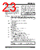
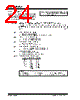
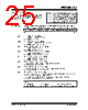
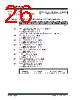
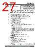
23 / 276 page  2004 Microchip Technology Inc. DS30498C-page 21 PIC16F7X7 2.2.2.1 Status Register The Status register contains the arithmetic status of the ALU, the Reset status and the bank select bits for data memory. The Status register can be the destination for any instruction, as with any other register. If the Status register is the destination for an instruction that affects the Z, DC or C bits, then the write to these three bits is disabled. These bits are set or cleared according to the device logic. Furthermore, the TO and PD bits are not writable, therefore, the result of an instruction with the Status register as destination may be different than intended. For example, CLRF STATUS, will clear the upper three bits and set the Z bit. This leaves the Status register as 000u u1uu (where u = unchanged). It is recommended, therefore, that only BCF, BSF, SWAPF and MOVWF instructions are used to alter the Status register because these instructions do not affect the Z, C or DC bits from the Status register. For other instructions not affecting any Status bits, see Section 16.0 “Instruction Set Summary”. REGISTER 2-1: STATUS: ARITHMETIC STATUS REGISTER (ADDRESS 03h, 83h, 103h, 183h) Note 1: The C and DC bits operate as a borrow and digit borrow bit, respectively, in subtraction. See the SUBLW and SUBWF instructions for examples. R/W-0 R/W-0 R/W-0 R-1 R-1 R/W-x R/W-x R/W-x IRP RP1 RP0 TO PD ZDC C bit 7 bit 0 bit 7 IRP: Register Bank Select bit (used for indirect addressing) 1 = Bank 2, 3 (100h-1FFh) 0 = Bank 0, 1 (00h-FFh) bit 6-5 RP1:RP0: Register Bank Select bits (used for direct addressing) 11 = Bank 3 (180h-1FFh) 10 = Bank 2 (100h-17Fh) 01 = Bank 1 (80h-FFh) 00 = Bank 0 (00h-7Fh) Each bank is 128 bytes. bit 4 TO: Time-out bit 1 = After power-up, CLRWDT instruction or SLEEP instruction 0 = A WDT time-out occurred bit 3 PD: Power-Down bit 1 = After power-up or by the CLRWDT instruction 0 = By execution of the SLEEP instruction bit 2 Z: Zero bit 1 = The result of an arithmetic or logic operation is zero 0 = The result of an arithmetic or logic operation is not zero bit 1 DC: Digit Carry/borrow bit (ADDWF, ADDLW, SUBLW, SUBWF instructions) 1 = A carry-out from the 4th low-order bit of the result occurred 0 = No carry-out from the 4th low-order bit of the result bit 0 C: Carry/borrow bit (ADDWF, ADDLW, SUBLW, SUBWF instructions) 1 = A carry-out from the Most Significant bit of the result occurred 0 = No carry-out from the Most Significant bit of the result occurred Note: For borrow, the polarity is reversed. A subtraction is executed by adding the two’s complement of the second operand. For rotate (RRF, RLF) instructions, this bit is loaded with either the high or low-order bit of the source register. Legend: R = Readable bit W = Writable bit U = Unimplemented bit, read as ‘0’ -n = Value at POR ‘1’ = Bit is set ‘0’ = Bit is cleared x = Bit is unknown |
|
Link URL |
| Does ALLDATASHEET help your business so far? [ DONATE ] |
About Alldatasheet | Advertisement | Contact us | Privacy Policy | Link to Datasheet | Link Exchange | Manufacturer List All Rights Reserved©Alldatasheet.com |
| Russian : Alldatasheetru.com | Korean : Alldatasheet.co.kr | Spanish : Alldatasheet.es | French : Alldatasheet.fr | Italian : Alldatasheetit.com Portuguese : Alldatasheetpt.com | Polish : Alldatasheet.pl | Vietnamese : Alldatasheet.vn Indian : Alldatasheet.in | Mexican : Alldatasheet.com.mx | British : Alldatasheet.co.uk | New Zealand : Alldatasheet.co.nz |
|
Family Site : ic2ic.com |
icmetro.com |
 New Zealand ▼
 English
 Chinese
 German
 Japanese
 Russian
 Korean
 Spanish
 French
 Italian
 Portuguese
 Polish
 Vietnamese
 Indian
 Mexican
 British
 New Zealand