|
Electronic Components Datasheet Search |
|
|
Electronic Components Datasheet Search |
|
PIC16F7X7 Datasheet(PDF) 75 Page - Microchip Technology |
|
|
|||||||||||||||||||||||||||||
PIC16F7X7 Datasheet(HTML) 75 Page - Microchip Technology |
|
|
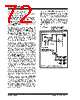
75 / 276 page  2004 Microchip Technology Inc. DS30498C-page 73 PIC16F7X7 6.0 TIMER0 MODULE The Timer0 module timer/counter has the following features: • 8-bit timer/counter • Readable and writable • 8-bit software programmable prescaler • Internal or external clock select • Interrupt on overflow from FFh to 00h • Edge select for external clock Additional information on the Timer0 module is available in the “PICmicro® Mid-Range MCU Family Reference Manual” (DS33023). Figure 6-1 is a block diagram of the Timer0 module and the prescaler shared with the WDT. 6.1 Timer0 Operation Timer0 operation is controlled through the OPTION_REG register (see Register 2-2). Timer mode is selected by clearing bit T0CS (OPTION_REG<5>). In Timer mode, the Timer0 module will increment every instruction cycle (without prescaler). If the TMR0 regis- ter is written, the increment is inhibited for the following two instruction cycles. The user can work around this by writing an adjusted value to the TMR0 register. Counter mode is selected by setting bit, T0CS (OPTION_REG<5>). In Counter mode, Timer0 will increment, either on every rising or falling edge of pin RA4/T0CKI/C1OUT. The incrementing edge is determined by the Timer0 Source Edge Select bit, T0SE (OPTION_REG<4>). Clearing bit T0SE selects the rising edge. Restrictions on the external clock input are discussed in detail in Section 6.3 “Using Timer0 With an External Clock”. The prescaler is mutually, exclusively shared between the Timer0 module and the Watchdog Timer. The prescaler is not readable or writable. Section 6.4 “Prescaler” details the operation of the prescaler. 6.2 Timer0 Interrupt The TMR0 interrupt is generated when the TMR0 reg- ister overflows from FFh to 00h. This overflow sets bit TMR0IF (INTCON<2>). The interrupt can be masked by clearing bit TMR0IE (INTCON<5>). Bit TMR0IF must be cleared in software by the Timer0 module Interrupt Service Routine before re-enabling this interrupt. The TMR0 interrupt cannot awaken the processor from Sleep since the timer is shut-off during Sleep. FIGURE 6-1: BLOCK DIAGRAM OF THE TIMER0/WDT PRESCALER RA4/T0CKI/C1OUT T0SE pin M U X CLKO (= FOSC/4) Sync 2 Cycles TMR0 Reg 8-bit Prescaler 8-to-1 MUX M U X MUX PSA 0 1 0 1 WDT Time-out PS2:PS0 8 Note: T0CS, T0SE, PSA and PS2:PS0 are (OPTION_REG<5:0>). PSA M U X 0 1 0 1 Data Bus Set Flag bit TMR0IF on Overflow 8 PSA T0CS Prescaler 31.25 kHz WDT Timer WDT Enable bit 16-bit Prescaler |
|
Link URL |
| Does ALLDATASHEET help your business so far? [ DONATE ] |
About Alldatasheet | Advertisement | Contact us | Privacy Policy | Link to Datasheet | Link Exchange | Manufacturer List All Rights Reserved©Alldatasheet.com |
| Russian : Alldatasheetru.com | Korean : Alldatasheet.co.kr | Spanish : Alldatasheet.es | French : Alldatasheet.fr | Italian : Alldatasheetit.com Portuguese : Alldatasheetpt.com | Polish : Alldatasheet.pl | Vietnamese : Alldatasheet.vn Indian : Alldatasheet.in | Mexican : Alldatasheet.com.mx | British : Alldatasheet.co.uk | New Zealand : Alldatasheet.co.nz |
|
Family Site : ic2ic.com |
icmetro.com |
 New Zealand ▼
 English
 Chinese
 German
 Japanese
 Russian
 Korean
 Spanish
 French
 Italian
 Portuguese
 Polish
 Vietnamese
 Indian
 Mexican
 British
 New Zealand