|
Electronic Components Datasheet Search |
|
|
Electronic Components Datasheet Search |
|
PIC16F7X7 Datasheet(PDF) 49 Page - Microchip Technology |
|
|
|||||||||||||||||||||||||||||
PIC16F7X7 Datasheet(HTML) 49 Page - Microchip Technology |
|
|
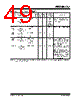
49 / 276 page  2004 Microchip Technology Inc. DS30498C-page 47 PIC16F7X7 TABLE 4-4: CLOCK SWITCHING MODES Current System Clock SCS bits<1:0> Modified to: Delay OSTS bit IOFS bit T1RUN bit New System Clock Comments LP, XT, HS, T1OSC, EC, RC 10 (INTRC) FOSC<2:0> = LP, XT or HS 8 Clocks of INTRC 01(1) 0 INTRC or INTOSC or INTOSC Postscaler The internal RC oscillator frequency is dependant upon the IRCF bits. LP, XT, HS, INTRC, EC, RC 01 (T1OSC) FOSC<2:0> = LP, XT or HS 8 Clocks of T1OSC 0 N/A 1 T1OSC T1OSCEN bit must be enabled. INTRC T1OSC 00 FOSC<2:0> = EC or FOSC<2:0> = RC 8 Clocks of EC or RC 1 N/A 0 EC or RC INTRC T1OSC 00 FOSC<2:0> = LP, XT, HS 1024 Clocks + 8 Clocks of LP, XT, HS 1 N/A 0 LP, XT, HS During the 1024 clocks, program execution is clocked from the secondary oscillator until the primary oscillator becomes stable. LP, XT, HS 00 (Due to Reset) LP, XT, HS 1024 Clocks 1 N/A 0 LP, XT, HS When a Reset occurs, there is no clock transition sequence. Instruction execution and/or peripheral operation is suspended unless Two-Speed Start-up mode is enabled, after which the INTRC will act as the system clock until the Oscillator Start-up Timer has expired. Note 1: If the new clock source is the INTOSC or INTOSC postscaler, then the IOFS bit will be set 4 ms (approx.) after the clock change. |
|
Link URL |
| Does ALLDATASHEET help your business so far? [ DONATE ] |
About Alldatasheet | Advertisement | Contact us | Privacy Policy | Link to Datasheet | Link Exchange | Manufacturer List All Rights Reserved©Alldatasheet.com |
| Russian : Alldatasheetru.com | Korean : Alldatasheet.co.kr | Spanish : Alldatasheet.es | French : Alldatasheet.fr | Italian : Alldatasheetit.com Portuguese : Alldatasheetpt.com | Polish : Alldatasheet.pl | Vietnamese : Alldatasheet.vn Indian : Alldatasheet.in | Mexican : Alldatasheet.com.mx | British : Alldatasheet.co.uk | New Zealand : Alldatasheet.co.nz |
|
Family Site : ic2ic.com |
icmetro.com |
 New Zealand ▼
 English
 Chinese
 German
 Japanese
 Russian
 Korean
 Spanish
 French
 Italian
 Portuguese
 Polish
 Vietnamese
 Indian
 Mexican
 British
 New Zealand