|
Electronic Components Datasheet Search |
|
|
Electronic Components Datasheet Search |
|
PIC16F7X7 Datasheet(PDF) 79 Page - Microchip Technology |
|
|
|||||||||||||||||||||||||||||
PIC16F7X7 Datasheet(HTML) 79 Page - Microchip Technology |
|
|
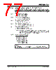
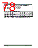
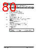
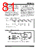
79 / 276 page  2004 Microchip Technology Inc. DS30498C-page 77 PIC16F7X7 7.0 TIMER1 MODULE The Timer1 module is a 16-bit timer/counter consisting of two 8-bit registers (TMR1H and TMR1L) which are readable and writable. The TMR1 register pair (TMR1H:TMR1L) increments from 0000h to FFFFh and rolls over to 0000h. The TMR1 interrupt, if enabled, is generated on overflow which is latched in interrupt flag bit, TMR1IF (PIR1<0>). This interrupt can be enabled/disabled by setting/clearing TMR1 interrupt enable bit, TMR1IE (PIE1<0>). The Timer1 oscillator can be used as a secondary clock source in low-power modes. When the T1RUN bit is set along with SCS<1:0> = 01, the Timer1 oscillator is pro- viding the system clock. If the Fail-Safe Clock Monitor is enabled and the Timer1 oscillator fails while providing the system clock, polling the T1RUN bit will indicate whether the clock is being provided by the Timer1 oscillator or another source. Timer1 can also be used to provide Real-Time Clock (RTC) functionality to applications with only a minimal addition of external components and code overhead. 7.1 Timer1 Operation Timer1 can operate in one of three modes: •as a Timer • as a Synchronous Counter • as an Asynchronous Counter The operating mode is determined by the clock select bit, TMR1CS (T1CON<1>). In Timer mode, Timer1 increments every instruction cycle. In Counter mode, it increments on every rising edge of the external clock input. Timer1 can be enabled/disabled by setting/clearing control bit, TMR1ON (T1CON<0>). Timer1 also has an internal “Reset input”. This Reset can be generated by the CCP1 module as the special event trigger (see Section 9.4 “Capture Mode”). Register 7-1 shows the Timer1 Control register. When the Timer1 oscillator is enabled (T1OSCEN is set), the RC0/T1OSO/T1CKI and RC1/T1OSI/CCP2 pins become inputs. That is, the TRISB<7:6> value is ignored and these pins read as ‘0’. Additional information on timer modules is available in the “PICmicro® Mid-Range MCU Family Reference Manual” (DS33023). |
|
Link URL |
| Does ALLDATASHEET help your business so far? [ DONATE ] |
About Alldatasheet | Advertisement | Contact us | Privacy Policy | Link to Datasheet | Link Exchange | Manufacturer List All Rights Reserved©Alldatasheet.com |
| Russian : Alldatasheetru.com | Korean : Alldatasheet.co.kr | Spanish : Alldatasheet.es | French : Alldatasheet.fr | Italian : Alldatasheetit.com Portuguese : Alldatasheetpt.com | Polish : Alldatasheet.pl | Vietnamese : Alldatasheet.vn Indian : Alldatasheet.in | Mexican : Alldatasheet.com.mx | British : Alldatasheet.co.uk | New Zealand : Alldatasheet.co.nz |
|
Family Site : ic2ic.com |
icmetro.com |
 New Zealand ▼
 English
 Chinese
 German
 Japanese
 Russian
 Korean
 Spanish
 French
 Italian
 Portuguese
 Polish
 Vietnamese
 Indian
 Mexican
 British
 New Zealand