|
Electronic Components Datasheet Search |
|
|
Electronic Components Datasheet Search |
|
PIC16F7X7 Datasheet(PDF) 58 Page - Microchip Technology |
|
|
|||||||||||||||||||||||||||||
PIC16F7X7 Datasheet(HTML) 58 Page - Microchip Technology |
|
|
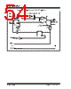
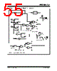
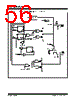
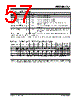
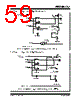
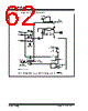
58 / 276 page  PIC16F7X7 DS30498C-page 56 2004 Microchip Technology Inc. 5.2 PORTB and the TRISB Register PORTB is an 8-bit wide, bidirectional port. The corre- sponding data direction register is TRISB. Setting a TRISB bit (= 1) will make the corresponding PORTB pin an input (i.e., put the corresponding output driver in a high-impedance mode). Clearing a TRISB bit (= 0) will make the corresponding PORTB pin an output (i.e., put the contents of the output latch on the selected pin). Each of the PORTB pins has a weak internal pull-up. A single control bit can turn on all the pull-ups. This is performed by clearing bit RBPU (OPTION_REG<7>). The weak pull-up is automatically turned off when the port pin is configured as an output. The pull-ups are disabled on a Power-on Reset. PORTB pins are multiplexed with analog inputs. The operation of each pin is selected by clearing/setting the appropriate control bits in the ADCON1 register. Four of the PORTB pins (RB7:RB4) have an interrupt- on-change feature. Only pins configured as inputs can cause this interrupt to occur (i.e., any RB7:RB4 pin configured as an output is excluded from the interrupt- on-change comparison). The input pins (of RB7:RB4) are compared with the old value latched on the last read of PORTB. The “mismatch” outputs of RB7:RB4 are ORed together to generate the RB port change interrupt with flag bit, RBIF (INTCON<0>). This interrupt can wake the device from Sleep. The user, in the Interrupt Service Routine, can clear the interrupt in the following manner: a) Any read or write of PORTB. This will end the mismatch condition. b) Clear flag bit RBIF. A mismatch condition will continue to set flag bit RBIF. Reading PORTB will end the mismatch condition and allow flag bit RBIF to be cleared. The interrupt-on-change feature is recommended for wake-up on key depression operation and operations where PORTB is only used for the interrupt-on-change feature. Polling of PORTB is not recommended while using the interrupt-on-change feature. This interrupt on mismatch feature, together with soft- ware configureable pull-ups on these four pins, allow easy interface to a keypad and make it possible for wake-up on key depression. Refer to the Application Note AN552 “Implementing Wake-up on Key Stroke” (DS00552). RB0/INT is an external interrupt input pin and is configured using the INTEDG bit (OPTION_REG<6>). RB0/INT is discussed in detail in Section 15.15.1 “INT Interrupt”. PORTB is multiplexed with several peripheral functions (see Table 5-3). PORTB pins have Schmitt Trigger input buffers. When enabling peripheral functions, care should be taken in defining TRIS bits for each PORTB pin. Some peripherals override the TRIS bit to make a pin an out- put, while other peripherals override the TRIS bit to make a pin an input. Since the TRIS bit override is in effect while the peripheral is enabled, read-modify- write instructions (BSF, BCF, XORWF) with TRISB as destination should be avoided. The user should refer to the corresponding peripheral section for the correct TRIS bit settings. Note: On a Power-on Reset, these pins are configured as analog inputs and read as ‘0’. |
|
Link URL |
| Does ALLDATASHEET help your business so far? [ DONATE ] |
About Alldatasheet | Advertisement | Contact us | Privacy Policy | Link to Datasheet | Link Exchange | Manufacturer List All Rights Reserved©Alldatasheet.com |
| Russian : Alldatasheetru.com | Korean : Alldatasheet.co.kr | Spanish : Alldatasheet.es | French : Alldatasheet.fr | Italian : Alldatasheetit.com Portuguese : Alldatasheetpt.com | Polish : Alldatasheet.pl | Vietnamese : Alldatasheet.vn Indian : Alldatasheet.in | Mexican : Alldatasheet.com.mx | British : Alldatasheet.co.uk | New Zealand : Alldatasheet.co.nz |
|
Family Site : ic2ic.com |
icmetro.com |
 New Zealand ▼
 English
 Chinese
 German
 Japanese
 Russian
 Korean
 Spanish
 French
 Italian
 Portuguese
 Polish
 Vietnamese
 Indian
 Mexican
 British
 New Zealand