|
Electronic Components Datasheet Search |
|
|
Electronic Components Datasheet Search |
|
PIC16F7X7 Datasheet(PDF) 89 Page - Microchip Technology |
|
|
|||||||||||||||||||||||||||||
PIC16F7X7 Datasheet(HTML) 89 Page - Microchip Technology |
|
|
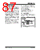
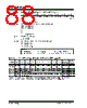
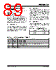
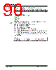
89 / 276 page  2004 Microchip Technology Inc. DS30498C-page 87 PIC16F7X7 9.0 CAPTURE/COMPARE/PWM MODULES Each Capture/Compare/PWM (CCP) module contains a 16-bit register which can operate as a: • 16-bit Capture register • 16-bit Compare register • PWM Master/Slave Duty Cycle register The CCP1, CCP2 and CCP3 modules are identical in operation, with the exception being the operation of the special event trigger. Table 9-1 and Table 9-2 show the resources and interactions of the CCP module(s). In the following sections, the operation of a CCP module is described with respect to CCP1. CCP2 and CCP3 operate the same as CCP1, except where noted. 9.1 CCP1 Module Capture/Compare/PWM Register 1 (CCPR1) is comprised of two 8-bit registers: CCPR1L (low byte) and CCPR1H (high byte). The CCP1CON register con- trols the operation of CCP1. The special event trigger is generated by a compare match and will clear both TMR1H and TMR1L registers. 9.2 CCP2 Module Capture/Compare/PWM Register 2 (CCPR2) is com- prised of two 8-bit registers: CCPR2L (low byte) and CCPR2H (high byte). The CCP2CON register controls the operation of CCP2. The special event trigger is gen- erated by a compare match; it will clear both TMR1H and TMR1L registers and start an A/D conversion (if the A/D module is enabled). Additional information on CCP modules is available in the “PICmicro® Mid-Range MCU Family Reference Manual” (DS33023) and in Application Note AN594 “Using the CCP Module(s)” (DS00594). 9.3 CCP3 Module Capture/Compare/PWM Register 3 (CCPR3) is com- prised of two 8-bit registers: CCPR3L (low byte) and CCPR3H (high byte). The CCP3CON register controls the operation of CCP3. TABLE 9-1: CCP MODE – TIMER RESOURCES REQUIRED TABLE 9-2: INTERACTION OF TWO CCP MODULES CCP Mode Timer Resource Capture Compare PWM Timer1 Timer1 Timer2 CCPx Mode CCPy Mode Interaction Capture Capture Same TMR1 time base. Capture Compare Same TMR1 time base. Compare Compare Same TMR1 time base. PWM PWM The PWMs will have the same frequency and update rate (TMR2 interrupt). The rising edges are aligned. PWM Capture None. PWM Compare None. |
|
Link URL |
| Does ALLDATASHEET help your business so far? [ DONATE ] |
About Alldatasheet | Advertisement | Contact us | Privacy Policy | Link to Datasheet | Link Exchange | Manufacturer List All Rights Reserved©Alldatasheet.com |
| Russian : Alldatasheetru.com | Korean : Alldatasheet.co.kr | Spanish : Alldatasheet.es | French : Alldatasheet.fr | Italian : Alldatasheetit.com Portuguese : Alldatasheetpt.com | Polish : Alldatasheet.pl | Vietnamese : Alldatasheet.vn Indian : Alldatasheet.in | Mexican : Alldatasheet.com.mx | British : Alldatasheet.co.uk | New Zealand : Alldatasheet.co.nz |
|
Family Site : ic2ic.com |
icmetro.com |
 New Zealand ▼
 English
 Chinese
 German
 Japanese
 Russian
 Korean
 Spanish
 French
 Italian
 Portuguese
 Polish
 Vietnamese
 Indian
 Mexican
 British
 New Zealand