|
Electronic Components Datasheet Search |
|
|
Electronic Components Datasheet Search |
|
PIC16F7X7 Datasheet(PDF) 47 Page - Microchip Technology |
|
|
|||||||||||||||||||||||||||||
PIC16F7X7 Datasheet(HTML) 47 Page - Microchip Technology |
|
|
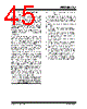
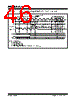
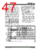
47 / 276 page  2004 Microchip Technology Inc. DS30498C-page 45 PIC16F7X7 4.7.3.2 Returning to Primary Oscillator with a Reset A Reset will clear SCS<1:0> back to ‘00’. The sequence for starting the primary oscillator following a Reset is the same for all forms of Reset, including POR. There is no transition sequence from the alternate system clock to the primary system clock on a Reset condition. Instead, the device will reset the state of the OSCCON register and default to the primary system clock. The sequence of events that take place after this will depend upon the value of the FOSC bits in the Configuration register. If the external oscillator is configured as a crystal (HS, XT or LP), the CPU will be held in the Q1 state until 1024 clock cycles have transpired on the primary clock. This is necessary because the crystal oscillator had been powered down until the time of the transition. During the oscillator start-up time, instruction execution and/or peripheral operation is suspended. If the primary system clock is either RC, EC or INTRC, the CPU will begin operating on the first Q1 cycle following the wake-up event. This means that there is no oscillator start-up time required because the primary clock is already stable; however, there is a delay between the wake-up event and the following Q2. An internal delay timer of 5-10 µs will suspend operation after the Reset to allow the CPU to become ready for code execution. The CPU and peripheral clock will be held in the first Q1. The sequence of events is as follows: 1. A device Reset is asserted from one of many sources (WDT, BOR, MCLR, etc.). 2. The device resets and the CPU start-up timer is enabled if in Sleep mode. The device is held in Reset until the CPU start-up time-out is complete. 3. If the primary system clock is configured as an external oscillator (HS, XT, LP), then the OST will be active waiting for 1024 clocks of the pri- mary system clock. While waiting for the OST, the device will be held in Reset. The OST and CPU start-up timers run in parallel. 4. After both the CPU start-up timer and the Oscillator Start-up Timer have timed out, the device will wait for one additional clock cycle and instruction execution will begin. FIGURE 4-10: TIMING LP CLOCK TO PRIMARY SYSTEM CLOCK AFTER RESET (HS, XT, LP) Note: If Two-Speed Clock Start-up mode is enabled, the INTRC will act as the system clock until the Oscillator Start-up Timer has timed out. Q4 Q1 Q3 Q4 Q1 Q2 OSC1 Peripheral Sleep Program PC 0000h T1OSI TOST(4) Q3 TT1P(1) Q4 OSC2 OSTS System Clock 0001h Q1 Q2 Q3 Q4 Q1 Q2 Clock Counter 0004h 0005h 0003h Q1 Q2 Q3 Q4 Reset TEPU(3) Note 1: TT1P = 30.52 µs. 2: TOSC = 50 ns minimum. 3: TEPU = 5-10 µs. 4: Refer to parameter D032 in Section 18.0 “Electrical Characteristics”. CPU Start-up TOSC(2) |
|
Link URL |
| Does ALLDATASHEET help your business so far? [ DONATE ] |
About Alldatasheet | Advertisement | Contact us | Privacy Policy | Link to Datasheet | Link Exchange | Manufacturer List All Rights Reserved©Alldatasheet.com |
| Russian : Alldatasheetru.com | Korean : Alldatasheet.co.kr | Spanish : Alldatasheet.es | French : Alldatasheet.fr | Italian : Alldatasheetit.com Portuguese : Alldatasheetpt.com | Polish : Alldatasheet.pl | Vietnamese : Alldatasheet.vn Indian : Alldatasheet.in | Mexican : Alldatasheet.com.mx | British : Alldatasheet.co.uk | New Zealand : Alldatasheet.co.nz |
|
Family Site : ic2ic.com |
icmetro.com |
 New Zealand ▼
 English
 Chinese
 German
 Japanese
 Russian
 Korean
 Spanish
 French
 Italian
 Portuguese
 Polish
 Vietnamese
 Indian
 Mexican
 British
 New Zealand