|
Electronic Components Datasheet Search |
|
|
Electronic Components Datasheet Search |
|
PIC16F7X7 Datasheet(PDF) 41 Page - Microchip Technology |
|
|
|||||||||||||||||||||||||||||
PIC16F7X7 Datasheet(HTML) 41 Page - Microchip Technology |
|
|
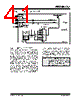
41 / 276 page  2004 Microchip Technology Inc. DS30498C-page 39 PIC16F7X7 FIGURE 4-6: PIC16F7X7 CLOCK DIAGRAM 4.6.4 MODIFYING THE IRCF BITS The IRCF bits can be modified at any time regardless of which clock source is currently being used as the system clock. The internal oscillator allows users to change the frequency during run time. This is achieved by modifying the IRCF bits in the OSCCON register. The sequence of events that occur after the IRCF bits are modified is dependent upon the initial value of the IRCF bits before they are modified. If the INTRC (31.25 kHz, IRCF<2:0> = 000) is running and the IRCF bits are modified to any other value than ‘000’, a 4 ms (approx.) clock switch delay is turned on. Code execu- tion continues at a higher than expected frequency while the new frequency stabilizes. Time sensitive code should wait for the IOFS bit in the OSCCON register to become set before continuing. This bit can be monitored to ensure that the frequency is stable before using the system clock in time critical applications. If the IRCF bits are modified while the internal oscillator is running at any other frequency than INTRC (31.25 kHz, IRCF<2:0> ≠ 000), there is no need for a 4 ms (approx.) clock switch delay. The new INTOSC frequency will be stable immediately after the eight falling edges. The IOFS bit will remain set after clock switching occurs. Secondary Oscillator T1OSCEN Enable Oscillator T1OSO T1OSI OSC1 OSC2 Sleep Primary Oscillator LP, XT, HS, RC, EC T1OSC CPU Peripherals 8 MHz 4 MHz 2 MHz 1 MHz 500 kHz 125 kHz 250 kHz OSCCON<6:4> 111 110 101 100 011 010 001 000 31.25 kHz 31.25 kHz Source Internal Oscillator Block WDT, FSCM 31.25 kHz 8 MHz Internal Oscillator (INTRC) (INTOSC) CONFIG1 (FOSC2:FOSC0) SCS<1:0> (T1OSC) To Timer1 Note: Caution must be taken when modifying the IRCF bits using BCF or BSF instructions. It is possible to modify the IRCF bits to a frequency that may be out of the VDD specification range; for example: VDD = 2.0V and IRCF = 111 (8 MHz). |
|
Link URL |
| Does ALLDATASHEET help your business so far? [ DONATE ] |
About Alldatasheet | Advertisement | Contact us | Privacy Policy | Link to Datasheet | Link Exchange | Manufacturer List All Rights Reserved©Alldatasheet.com |
| Russian : Alldatasheetru.com | Korean : Alldatasheet.co.kr | Spanish : Alldatasheet.es | French : Alldatasheet.fr | Italian : Alldatasheetit.com Portuguese : Alldatasheetpt.com | Polish : Alldatasheet.pl | Vietnamese : Alldatasheet.vn Indian : Alldatasheet.in | Mexican : Alldatasheet.com.mx | British : Alldatasheet.co.uk | New Zealand : Alldatasheet.co.nz |
|
Family Site : ic2ic.com |
icmetro.com |
 New Zealand ▼
 English
 Chinese
 German
 Japanese
 Russian
 Korean
 Spanish
 French
 Italian
 Portuguese
 Polish
 Vietnamese
 Indian
 Mexican
 British
 New Zealand