|
Electronic Components Datasheet Search |
|
|
Electronic Components Datasheet Search |
|
PIC16F7X7 Datasheet(PDF) 37 Page - Microchip Technology |
|
|
|||||||||||||||||||||||||||||
PIC16F7X7 Datasheet(HTML) 37 Page - Microchip Technology |
|
|
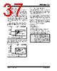
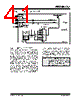
37 / 276 page  2004 Microchip Technology Inc. DS30498C-page 35 PIC16F7X7 4.4 RC Oscillator For timing insensitive applications, the “RC” and “RCIO” device options offer additional cost savings. The RC oscillator frequency is a function of the supply voltage, the resistor (REXT) and capacitor (CEXT) values and the operating temperature. In addition to this, the oscillator frequency will vary from unit to unit due to normal manufacturing variation. Furthermore, the difference in lead frame capacitance between package types will also affect the oscillation frequency, especially for low CEXT values. The user also needs to take into account varia- tion due to tolerance of external R and C components used. Figure 4-4 shows how the R/C combination is connected. In the RC Oscillator mode, the oscillator frequency divided by 4 is available on the OSC2 pin. This signal may be used for test purposes or to synchronize other logic. FIGURE 4-4: RC OSCILLATOR MODE The RCIO Oscillator mode (Figure 4-5) functions like the RC mode, except that the OSC2 pin becomes an additional general purpose I/O pin. The I/O pin becomes bit 6 of PORTA (RA6). FIGURE 4-5: RCIO OSCILLATOR MODE 4.5 Internal Oscillator Block The PIC16F7X7 devices include an internal oscillator block which generates two different clock signals; either can be used as the system’s clock source. This can eliminate the need for external oscillator circuits on the OSC1 and/or OSC2 pins. The main output (INTOSC) is an 8 MHz clock source which can be used to directly drive the system clock. It also drives the INTOSC postscaler which can provide a range of six clock frequencies, from 125 kHz to 4 MHz. The other clock source is the internal RC oscillator (INTRC) which provides a 31.25 kHz (32 µs nominal period) output. The INTRC oscillator is enabled by selecting the INTRC as the system clock source or when any of the following are enabled: • Power-up Timer • Watchdog Timer • Two-Speed Start-up • Fail-Safe Clock Monitor These features are discussed in greater detail in Section 15.0 “Special Features of the CPU”. The clock source frequency (INTOSC direct, INTRC direct or INTOSC postscaler) is selected by configuring the IRCF bits of the OSCCON register (page 38). OSC2/CLKO CEXT REXT PIC16F7X7 OSC1 FOSC/4 Internal Clock VDD VSS Recommended values: 3 k Ω ≤ REXT ≤ 100 kΩ CEXT > 20 pF CEXT REXT PIC16F7X7 OSC1 Internal Clock VDD VSS Recommended values: 3 k Ω ≤ REXT ≤ 100 kΩ CEXT > 20 pF I/O (OSC2) RA6 Note: Throughout this data sheet, when referring specifically to a generic clock source, the term “INTRC” may also be used to refer to the clock modes using the internal oscillator block. This is regardless of whether the actual frequency used is INTOSC (8 MHz), the INTOSC postscaler or INTRC (31.25 kHz). |
|
Link URL |
| Does ALLDATASHEET help your business so far? [ DONATE ] |
About Alldatasheet | Advertisement | Contact us | Privacy Policy | Link to Datasheet | Link Exchange | Manufacturer List All Rights Reserved©Alldatasheet.com |
| Russian : Alldatasheetru.com | Korean : Alldatasheet.co.kr | Spanish : Alldatasheet.es | French : Alldatasheet.fr | Italian : Alldatasheetit.com Portuguese : Alldatasheetpt.com | Polish : Alldatasheet.pl | Vietnamese : Alldatasheet.vn Indian : Alldatasheet.in | Mexican : Alldatasheet.com.mx | British : Alldatasheet.co.uk | New Zealand : Alldatasheet.co.nz |
|
Family Site : ic2ic.com |
icmetro.com |
 New Zealand ▼
 English
 Chinese
 German
 Japanese
 Russian
 Korean
 Spanish
 French
 Italian
 Portuguese
 Polish
 Vietnamese
 Indian
 Mexican
 British
 New Zealand