|
Electronic Components Datasheet Search |
|
|
Electronic Components Datasheet Search |
|
PIC16F7X7 Datasheet(PDF) 27 Page - Microchip Technology |
|
|
|||||||||||||||||||||||||||||
PIC16F7X7 Datasheet(HTML) 27 Page - Microchip Technology |
|
|
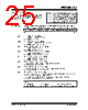
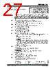
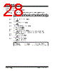
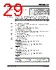
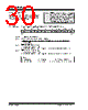
27 / 276 page  2004 Microchip Technology Inc. DS30498C-page 25 PIC16F7X7 2.2.2.5 PIR1 Register The PIR1 register contains the individual flag bits for the peripheral interrupts. REGISTER 2-5: PIR1: PERIPHERAL INTERRUPT REQUEST (FLAG) REGISTER 1 (ADDRESS 0Ch) Note: Interrupt flag bits are set when an interrupt condition occurs regardless of the state of its corresponding enable bit or the Global Inter- rupt Enable bit, GIE (INTCON<7>). User software should ensure the appropriate inter- rupt bits are clear prior to enabling an interrupt. R/W-0 R/W-0 R-0 R-0 R/W-0 R/W-0 R/W-0 R/W-0 PSPIF(1) ADIF RCIF TXIF SSPIF CCP1IF TMR2IF TMR1IF bit 7 bit 0 bit 7 PSPIF: Parallel Slave Port Read/Write Interrupt Flag bit(1) 1 = A read or a write operation has taken place (must be cleared in software) 0 = No read or write has occurred Note: PSPIF is reserved on 28-pin devices; always maintain this bit clear. bit 6 ADIF: A/D Converter Interrupt Flag bit 1 = An A/D conversion is completed (must be cleared in software) 0 = The A/D conversion is not complete bit 5 RCIF: AUSART Receive Interrupt Flag bit 1 = The AUSART receive buffer is full 0 = The AUSART receive buffer is empty bit 4 TXIF: AUSART Transmit Interrupt Flag bit 1 = The AUSART transmit buffer is empty 0 = The AUSART transmit buffer is full bit 3 SSPIF: Synchronous Serial Port (SSP) Interrupt Flag bit 1 = The SSP interrupt condition has occurred and must be cleared in software before returning from the Interrupt Service Routine. The conditions that will set this bit are: SPI: A transmission/reception has taken place. I2C Slave: A transmission/reception has taken place. I2C Master: A transmission/reception has taken place. The initiated Start condition was completed by the SSP module. The initiated Stop condition was completed by the SSP module. The initiated Restart condition was completed by the SSP module.The initiated Acknowledge condition was completed by the SSP module. A Start condition occurred while the SSP module was Idle (multi-master system). A Stop condition occurred while the SSP module was Idle (multi-master system). 0 = No SSP interrupt condition has occurred bit 2 CCP1IF: CCP1 Interrupt Flag bit Capture mode: 1 = A TMR1 register capture occurred (must be cleared in software) 0 = No TMR1 register capture occurred Compare mode: 1 = A TMR1 register compare match occurred (must be cleared in software) 0 = No TMR1 register compare match occurred PWM mode: Unused in this mode. bit 1 TMR2IF: TMR2 to PR2 Match Interrupt Flag bit 1 = TMR2 to PR2 match occurred (must be cleared in software) 0 = No TMR2 to PR2 match occurred bit 0 TMR1IF: TMR1 Overflow Interrupt Flag bit 1 = TMR1 register overflowed (must be cleared in software) 0 = TMR1 register did not overflow Legend: R = Readable bit W = Writable bit U = Unimplemented bit, read as ‘0’ -n = Value at POR ‘1’ = Bit is set ‘0’ = Bit is cleared x = Bit is unknown |
|
Link URL |
| Does ALLDATASHEET help your business so far? [ DONATE ] |
About Alldatasheet | Advertisement | Contact us | Privacy Policy | Link to Datasheet | Link Exchange | Manufacturer List All Rights Reserved©Alldatasheet.com |
| Russian : Alldatasheetru.com | Korean : Alldatasheet.co.kr | Spanish : Alldatasheet.es | French : Alldatasheet.fr | Italian : Alldatasheetit.com Portuguese : Alldatasheetpt.com | Polish : Alldatasheet.pl | Vietnamese : Alldatasheet.vn Indian : Alldatasheet.in | Mexican : Alldatasheet.com.mx | British : Alldatasheet.co.uk | New Zealand : Alldatasheet.co.nz |
|
Family Site : ic2ic.com |
icmetro.com |
 New Zealand ▼
 English
 Chinese
 German
 Japanese
 Russian
 Korean
 Spanish
 French
 Italian
 Portuguese
 Polish
 Vietnamese
 Indian
 Mexican
 British
 New Zealand