|
Electronic Components Datasheet Search |
|
|
Electronic Components Datasheet Search |
|
PIC16F7X7 Datasheet(PDF) 42 Page - Microchip Technology |
|
|
|||||||||||||||||||||||||||||
PIC16F7X7 Datasheet(HTML) 42 Page - Microchip Technology |
|
|
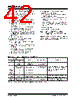
42 / 276 page  PIC16F7X7 DS30498C-page 40 2004 Microchip Technology Inc. 4.6.5 CLOCK TRANSITION SEQUENCE The following are three different sequences for switching the internal RC oscillator frequency: • Clock before switch: 31.25 kHz (IRCF<2:0> = 000) 1. IRCF bits are modified to an INTOSC/INTOSC postscaler frequency. 2. The clock switching circuitry waits for a falling edge of the current clock, at which point CLKO is held low. 3. The clock switching circuitry then waits for eight falling edges of requested clock, after which it switches CLKO to this new clock source. 4. The IOFS bit is clear to indicate that the clock is unstable and a 4 ms (approx.) delay is started. Time dependent code should wait for IOFS to become set. 5. Switchover is complete. • Clock before switch: One of INTOSC/INTOSC postscaler (IRCF<2:0> ≠ 000) 1. IRCF bits are modified to INTRC (IRCF<2:0> = 000). 2. The clock switching circuitry waits for a falling edge of the current clock, at which point CLKO is held low. 3. The clock switching circuitry then waits for eight falling edges of requested clock, after which it switches CLKO to this new clock source. 4. Oscillator switchover is complete. • Clock before switch: One of INTOSC/INTOSC postscaler (IRCF<2:0> ≠ 000) 1. IRCF bits are modified to a different INTOSC/ INTOSC postscaler frequency. 2. The clock switching circuitry waits for a falling edge of the current clock, at which point CLKO is held low. 3. The clock switching circuitry then waits for eight falling edges of requested clock, after which it switches CLKO to this new clock source. 4. The IOFS bit is set. 5. Oscillator switchover is complete. 4.6.6 OSCILLATOR DELAY UPON POWER-UP, WAKE-UP AND CLOCK SWITCHING Table 4-3 shows the different delays invoked for various clock switching sequences. It also shows the delays invoked for POR and wake-up. TABLE 4-3: OSCILLATOR DELAY EXAMPLES Clock Switch Frequency Oscillator Delay Comments From To Sleep/POR INTRC T1OSC 31.25 kHz 32.768 kHz CPU Start-up(1) Following a wake-up from Sleep mode or POR, CPU start-up is invoked to allow the CPU to become ready for code execution. INTOSC/INTOSC Postscaler 125 kHz-8 MHz 4 ms (approx.) and CPU Start-up(1) INTRC/ Sleep EC, RC DC – 20 MHz INTRC (31.25 kHz) EC, RC DC – 20 MHz Sleep LP, XT, HS 32.768 kHz-20 MHz 1024 Clock Cycles Following a change from INTRC, the OST count of 1024 cycles must occur. INTRC (31.25 kHz) INTOSC/INTOSC Postscaler 125 kHz-8 MHz 4 ms (approx.) Refer to Section 4.6.4 “Modifying the IRCF Bits” for further details. Note 1: The 5 µs-10 µs start-up delay is based on a 1 MHz system clock. |
|
Link URL |
| Does ALLDATASHEET help your business so far? [ DONATE ] |
About Alldatasheet | Advertisement | Contact us | Privacy Policy | Link to Datasheet | Link Exchange | Manufacturer List All Rights Reserved©Alldatasheet.com |
| Russian : Alldatasheetru.com | Korean : Alldatasheet.co.kr | Spanish : Alldatasheet.es | French : Alldatasheet.fr | Italian : Alldatasheetit.com Portuguese : Alldatasheetpt.com | Polish : Alldatasheet.pl | Vietnamese : Alldatasheet.vn Indian : Alldatasheet.in | Mexican : Alldatasheet.com.mx | British : Alldatasheet.co.uk | New Zealand : Alldatasheet.co.nz |
|
Family Site : ic2ic.com |
icmetro.com |
 New Zealand ▼
 English
 Chinese
 German
 Japanese
 Russian
 Korean
 Spanish
 French
 Italian
 Portuguese
 Polish
 Vietnamese
 Indian
 Mexican
 British
 New Zealand