|
Electronic Components Datasheet Search |
|
|
Electronic Components Datasheet Search |
|
PIC16F7X7 Datasheet(PDF) 265 Page - Microchip Technology |
|
|
|||||||||||||||||||||||||||||
PIC16F7X7 Datasheet(HTML) 265 Page - Microchip Technology |
|
|
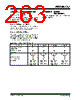
265 / 276 page  2004 Microchip Technology Inc. DS30498C-page 263 PIC16F7X7 INDEX A A/D A/D Converter Interrupt, Configuring ........................ 155 Acquisition Requirements ......................................... 156 ADRESH Register..................................................... 154 Analog Port Pins ......................................................... 68 Analog-to-Digital Converter....................................... 151 Associated Registers ................................................ 160 Automatic Acquisition Time....................................... 157 Calculating Acquisition Time..................................... 156 Configuring Analog Port Pins.................................... 158 Configuring the Module............................................. 155 Conversion Clock...................................................... 157 Conversion Requirements ........................................ 236 Conversion Status (GO/DONE Bit) ........................... 154 Conversions .............................................................. 159 Delays ....................................................................... 156 Effects of a Reset...................................................... 160 Internal Sampling Switch (Rss) Impedance ........................................................ 156 Operation During Sleep ............................................ 160 Operation in Power-Managed Modes ....................... 158 Source Impedance.................................................... 156 Time Delays .............................................................. 156 Use of the CCP Trigger............................................. 160 Absolute Maximum Ratings .............................................. 207 ACKSTAT ......................................................................... 123 ACKSTAT Status Flag ...................................................... 123 ADCON0 Register GO/DONE Bit............................................................ 154 Addressable Universal Synchronous Asynchronous Receiver Transmitter. See AUSART ADRESL Register ............................................................. 154 Application Notes AN546 (Using the Analog-to-Digital (A/D) Converter) ......................................................... 151 AN552 (Implementing Wake-up on Key Stroke) .................................................... 56 AN556 (Implementing a Table Read) ......................... 29 AN607 (Power-up Trouble Shooting)........................ 173 Assembler MPASM Assembler................................................... 201 AUSART Address Detect Enable (ADDEN Bit) ........................ 134 Addressable Universal Synchronous Asynchronous Receiver Transmitter................. 133 Asynchronous Receiver (9-Bit Mode) .............................................. 142 Asynchronous Mode ................................................. 138 Receiver............................................................ 140 Transmitter........................................................ 138 Asynchronous Receive with Address Detect. See Asynchronous Receive (9-bit Mode). Asynchronous Reception Associated Registers ................................ 141, 143 Setup ................................................................ 141 Asynchronous Reception with Address Detect Setup ................................................................ 142 Asynchronous Transmission Associated Registers........................................ 139 Setup ................................................................ 139 Baud Rate Generator (BRG) .................................... 135 Associated Registers........................................ 135 Baud Rate Formula .......................................... 135 Baud Rates, Asynchronous Mode (BRGH = 0)............................................... 136 Baud Rates, Asynchronous Mode (BRGH = 1)............................................... 136 High Baud Rate Select (BRGH Bit) .................. 133 INTRC Baud Rates, Asynchronous Mode (BRGH = 0)............................................... 137 INTRC Baud Rates, Asynchronous Mode (BRGH = 1)............................................... 137 Sampling .......................................................... 135 Clock Source Select (CSRC Bit) .............................. 133 Continuous Receive Enable (CREN Bit)........................................................ 134 Framing Error (FERR Bit) ......................................... 134 Overrun Error (OERR Bit)......................................... 134 Receive Data, 9th Bit (RX9D Bit).............................. 134 Receive Enable, 9-Bit (RX9 Bit) ............................... 134 Serial Port Enable (SPEN Bit) .......................... 133, 134 Single Receive Enable (SREN Bit)........................... 134 Synchronous Master Mode....................................... 144 Reception ......................................................... 146 Transmission .................................................... 144 Synchronous Master Reception Associated Registers........................................ 146 Setup ................................................................ 146 Synchronous Master Transmission Associated Registers........................................ 145 Setup ................................................................ 144 Synchronous Slave Mode......................................... 148 Reception ......................................................... 149 Transmit............................................................ 148 Synchronous Slave Reception Associated Registers........................................ 149 Setup ................................................................ 149 Synchronous Slave Transmission Associated Registers........................................ 148 Setup ................................................................ 148 Transmit Data, 9th Bit (TX9D) .................................. 133 Transmit Enable (TXEN Bit) ..................................... 133 Transmit Enable, 9-Bit (TX9 Bit)............................... 133 Transmit Shift Register Status (TRMT Bit) ........................................................ 133 B Banking, Data Memory ....................................................... 15 Baud Rate Generator ....................................................... 119 BF ..................................................................................... 123 BF Status Flag .................................................................. 123 |
|
Link URL |
| Does ALLDATASHEET help your business so far? [ DONATE ] |
About Alldatasheet | Advertisement | Contact us | Privacy Policy | Link to Datasheet | Link Exchange | Manufacturer List All Rights Reserved©Alldatasheet.com |
| Russian : Alldatasheetru.com | Korean : Alldatasheet.co.kr | Spanish : Alldatasheet.es | French : Alldatasheet.fr | Italian : Alldatasheetit.com Portuguese : Alldatasheetpt.com | Polish : Alldatasheet.pl | Vietnamese : Alldatasheet.vn Indian : Alldatasheet.in | Mexican : Alldatasheet.com.mx | British : Alldatasheet.co.uk | New Zealand : Alldatasheet.co.nz |
|
Family Site : ic2ic.com |
icmetro.com |
 New Zealand ▼
 English
 Chinese
 German
 Japanese
 Russian
 Korean
 Spanish
 French
 Italian
 Portuguese
 Polish
 Vietnamese
 Indian
 Mexican
 British
 New Zealand