|
Electronic Components Datasheet Search |
|
|
Electronic Components Datasheet Search |
|
PIC16F7X7 Datasheet(PDF) 135 Page - Microchip Technology |
|
|
|||||||||||||||||||||||||||||
PIC16F7X7 Datasheet(HTML) 135 Page - Microchip Technology |
|
|
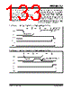
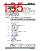
135 / 276 page  2004 Microchip Technology Inc. DS30498C-page 133 PIC16F7X7 11.0 ADDRESSABLE UNIVERSAL SYNCHRONOUS ASYNCHRONOUS RECEIVER TRANSMITTER (AUSART) The Addressable Universal Synchronous Asynchronous Receiver Transmitter (AUSART) module is one of the two serial I/O modules. (AUSART is also known as a Serial Communications Interface or SCI.) The AUSART can be configured as a full-duplex asynchronous system that can communicate with peripheral devices, such as CRT terminals and personal computers, or it can be configured as a half-duplex synchronous system that can communicate with peripheral devices, such as A/D or D/A integrated circuits, serial EEPROMs, etc. The AUSART can be configured in the following modes: • Asynchronous (full-duplex) • Synchronous – Master (half-duplex) • Synchronous – Slave (half-duplex) Bit SPEN (RCSTA<7>) and bits TRISC<7:6> have to be set in order to configure pins RC6/TX/CK and RC7/RX/DT as the Universal Synchronous Asynchronous Receiver Transmitter. The AUSART module also has a multi-processor communication capability using 9-bit address detection. REGISTER 11-1: TXSTA: TRANSMIT STATUS AND CONTROL REGISTER (ADDRESS 98h) R/W-0 R/W-0 R/W-0 R/W-0 U-0 R/W-0 R-1 R/W-0 CSRC TX9 TXEN SYNC — BRGH TRMT TX9D bit 7 bit 0 bit 7 CSRC: Clock Source Select bit Asynchronous mode: Don’t care. Synchronous mode: 1 = Master mode (clock generated internally from BRG) 0 = Slave mode (clock from external source) bit 6 TX9: 9-bit Transmit Enable bit 1 = Selects 9-bit transmission 0 = Selects 8-bit transmission bit 5 TXEN: Transmit Enable bit 1 = Transmit enabled 0 = Transmit disabled Note: SREN/CREN overrides TXEN in Sync mode. bit 4 SYNC: AUSART Mode Select bit 1 = Synchronous mode 0 = Asynchronous mode bit 3 Unimplemented: Read as ‘0’ bit 2 BRGH: High Baud Rate Select bit Asynchronous mode: 1 = High speed 0 = Low speed Synchronous mode: Unused in this mode. bit 1 TRMT: Transmit Shift Register Status bit 1 = TSR empty 0 = TSR full bit 0 TX9D: 9th bit of Transmit Data, can be Parity bit Legend: R = Readable bit W = Writable bit U = Unimplemented bit, read as ‘0’ -n = Value at POR ‘1’ = Bit is set ‘0’ = Bit is cleared x = Bit is unknown |
|
Link URL |
| Does ALLDATASHEET help your business so far? [ DONATE ] |
About Alldatasheet | Advertisement | Contact us | Privacy Policy | Link to Datasheet | Link Exchange | Manufacturer List All Rights Reserved©Alldatasheet.com |
| Russian : Alldatasheetru.com | Korean : Alldatasheet.co.kr | Spanish : Alldatasheet.es | French : Alldatasheet.fr | Italian : Alldatasheetit.com Portuguese : Alldatasheetpt.com | Polish : Alldatasheet.pl | Vietnamese : Alldatasheet.vn Indian : Alldatasheet.in | Mexican : Alldatasheet.com.mx | British : Alldatasheet.co.uk | New Zealand : Alldatasheet.co.nz |
|
Family Site : ic2ic.com |
icmetro.com |
 New Zealand ▼
 English
 Chinese
 German
 Japanese
 Russian
 Korean
 Spanish
 French
 Italian
 Portuguese
 Polish
 Vietnamese
 Indian
 Mexican
 British
 New Zealand