|
Electronic Components Datasheet Search |
|
|
Electronic Components Datasheet Search |
|
PIC16F7X7 Datasheet(PDF) 217 Page - Microchip Technology |
|
|
|||||||||||||||||||||||||||||
PIC16F7X7 Datasheet(HTML) 217 Page - Microchip Technology |
|
|
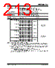
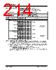
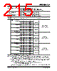
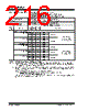
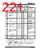
217 / 276 page  2004 Microchip Technology Inc. DS30498C-page 215 PIC16F7X7 Module Differential Currents ( ∆IWDT, ∆IBOR, ∆ILVD, ∆IOSCB, ∆IAD) D022 ( ∆IWDT) Watchdog Timer 1.5 3.8 µA -40°C VDD = 2.0V 2.2 3.8 µA+25°C 2.7 4.0 µA+85°C 2.3 4.6 µA -40°C VDD = 3.0V 2.7 4.6 µA+25°C 3.1 4.8 µA+85°C 3.0 10.0 µA -40°C VDD = 5.0V 3.3 10.0 µA+25°C 3.9 13.0 µA+85°C Extended devices 5.0 21.0 µA +125°C D022A ( ∆IBOR) Brown-out Reset 17 35 µA-40°C to +85°CVDD = 3.0V 47 45 µA-40°C to +85°CVDD = 5.0V 00 µA-40°C to +85°CVDD = 2.0V VDD = 3.0V VDD = 5.0V BOREN:BORSEN = 10 in Sleep mode Extended devices 48 50 µA-40°C to +125°CVDD = 5.0V D022B ( ∆ILVD) Low-Voltage Detect 14 25 µA-40°C to +85°CVDD = 2.0V 18 35 µA-40°C to +85°CVDD = 3.0V 21 45 µA-40°C to +85°CVDD = 5.0V Extended devices 24 50 µA-40°C to +125°CVDD = 5.0V 18.2 DC Characteristics: Power-Down and Supply Current PIC16F737/747/767/777 (Industrial, Extended) PIC16LF737/747/767/777 (Industrial) (Continued) PIC16LF737/747/767/777 (Industrial) Standard Operating Conditions (unless otherwise stated) Operating temperature -40°C ≤ TA ≤ +85°C for industrial PIC16F737/747/767/777 (Industrial, Extended) Standard Operating Conditions (unless otherwise stated) Operating temperature -40°C ≤ TA ≤ +85°C for industrial -40°C ≤ TA ≤ +125°C for extended Param No. Device Typ Max Units Conditions Legend: Shading of rows is to assist in readability of the table. Note 1: The power-down current in Sleep mode does not depend on the oscillator type. Power-down current is measured with the part in Sleep mode, with all I/O pins in high-impedance state and tied to VDD or VSS and all features that add delta current disabled (such as WDT, Timer1 Oscillator, BOR, etc.). 2: The supply current is mainly a function of operating voltage, frequency and mode. Other factors, such as I/O pin loading and switching rate, oscillator type and circuit, internal code execution pattern and temperature, also have an impact on the current consumption. The test conditions for all IDD measurements in active operation mode are: OSC1 = external square wave, from rail-to-rail; all I/O pins tri-stated, pulled to VDD; MCLR = VDD; WDT enabled/disabled as specified. 3: For RC oscillator configurations, current through REXT is not included. The current through the resistor can be estimated by the formula Ir = VDD/2REXT (mA) with REXT in k Ω. |
|
Link URL |
| Does ALLDATASHEET help your business so far? [ DONATE ] |
About Alldatasheet | Advertisement | Contact us | Privacy Policy | Link to Datasheet | Link Exchange | Manufacturer List All Rights Reserved©Alldatasheet.com |
| Russian : Alldatasheetru.com | Korean : Alldatasheet.co.kr | Spanish : Alldatasheet.es | French : Alldatasheet.fr | Italian : Alldatasheetit.com Portuguese : Alldatasheetpt.com | Polish : Alldatasheet.pl | Vietnamese : Alldatasheet.vn Indian : Alldatasheet.in | Mexican : Alldatasheet.com.mx | British : Alldatasheet.co.uk | New Zealand : Alldatasheet.co.nz |
|
Family Site : ic2ic.com |
icmetro.com |
 New Zealand ▼
 English
 Chinese
 German
 Japanese
 Russian
 Korean
 Spanish
 French
 Italian
 Portuguese
 Polish
 Vietnamese
 Indian
 Mexican
 British
 New Zealand