|
Electronic Components Datasheet Search |
|
|
Electronic Components Datasheet Search |
|
PIC16F7X7 Datasheet(PDF) 106 Page - Microchip Technology |
|
|
|||||||||||||||||||||||||||||
PIC16F7X7 Datasheet(HTML) 106 Page - Microchip Technology |
|
|
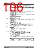
106 / 276 page  PIC16F7X7 DS30498C-page 104 2004 Microchip Technology Inc. REGISTER 10-4: SSPCON: MSSP CONTROL (I2C MODE) REGISTER 1 (ADDRESS 14h) R/W-0 R/W-0 R/W-0 R/W-0 R/W-0 R/W-0 R/W-0 R/W-0 WCOL SSPOV SSPEN CKP SSPM3 SSPM2 SSPM1 SSPM0 bit 7 bit 0 bit 7 WCOL: Write Collision Detect bit In Master Transmit mode: 1 = A write to the SSPBUF register was attempted while the I2C conditions were not valid for a transmission to be started (must be cleared in software) 0 = No collision In Slave Transmit mode: 1 = The SSPBUF register is written while it is still transmitting the previous word (must be cleared in software) 0 = No collision In Receive mode (Master or Slave modes): This is a “don’t care” bit. bit 6 SSPOV: Receive Overflow Indicator bit In Receive mode: 1 = A byte is received while the SSPBUF register is still holding the previous byte (must be cleared in software) 0 = No overflow In Transmit mode: This is a “don’t care” bit in Transmit mode. bit 5 SSPEN: Synchronous Serial Port Enable bit 1 = Enables the serial port and configures the SDA and SCL pins as the serial port pins 0 = Disables serial port and configures these pins as I/O port pins Note: When enabled, the SDA and SCL pins must be properly configured as input or output. bit 4 CKP: SCK Release Control bit In Slave mode: 1 = Release clock 0 = Holds clock low (clock stretch). (Used to ensure data setup time.) In Master mode: Unused in this mode. bit 3-0 SSPM3:SSPM0: Synchronous Serial Port Mode Select bits 1111 = I2C Slave mode, 10-bit address with Start and Stop bit interrupts enabled 1110 = I2C Slave mode, 7-bit address with Start and Stop bit interrupts enabled 1011 = I2C Firmware Controlled Master mode (slave Idle) 1000 = I2C Master mode, clock = FOSC/(4 * (SSPADD + 1)) 0111 = I2C Slave mode, 10-bit address 0110 = I2C Slave mode, 7-bit address Note: Bit combinations not specifically listed here are either reserved or implemented in SPI mode only. Legend: R = Readable bit W = Writable bit U = Unimplemented bit, read as ‘0’ -n = Value at POR ‘1’ = Bit is set ‘0’ = Bit is cleared x = Bit is unknown |
|
Link URL |
| Does ALLDATASHEET help your business so far? [ DONATE ] |
About Alldatasheet | Advertisement | Contact us | Privacy Policy | Link to Datasheet | Link Exchange | Manufacturer List All Rights Reserved©Alldatasheet.com |
| Russian : Alldatasheetru.com | Korean : Alldatasheet.co.kr | Spanish : Alldatasheet.es | French : Alldatasheet.fr | Italian : Alldatasheetit.com Portuguese : Alldatasheetpt.com | Polish : Alldatasheet.pl | Vietnamese : Alldatasheet.vn Indian : Alldatasheet.in | Mexican : Alldatasheet.com.mx | British : Alldatasheet.co.uk | New Zealand : Alldatasheet.co.nz |
|
Family Site : ic2ic.com |
icmetro.com |
 New Zealand ▼
 English
 Chinese
 German
 Japanese
 Russian
 Korean
 Spanish
 French
 Italian
 Portuguese
 Polish
 Vietnamese
 Indian
 Mexican
 British
 New Zealand