|
Electronic Components Datasheet Search |
|
|
Electronic Components Datasheet Search |
|
PIC16F7X7 Datasheet(PDF) 150 Page - Microchip Technology |
|
|
|||||||||||||||||||||||||||||
PIC16F7X7 Datasheet(HTML) 150 Page - Microchip Technology |
|
|
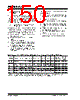
150 / 276 page  PIC16F7X7 DS30498C-page 148 2004 Microchip Technology Inc. 11.4 AUSART Synchronous Slave Mode Synchronous Slave mode differs from the Master mode in the fact that the shift clock is supplied externally at the RC6/TX/CK pin (instead of being supplied internally in Master mode). This allows the device to transfer or receive data while in Sleep mode. Slave mode is entered by clearing bit, CSRC (TXSTA<7>). 11.4.1 AUSART SYNCHRONOUS SLAVE TRANSMIT The operation of the Synchronous Master and Slave modes is identical, except in the case of Sleep mode. If two words are written to the TXREG and then the SLEEP instruction is executed, the following will occur: a) The first word will immediately transfer to the TSR register and transmit. b) The second word will remain in the TXREG register. c) Flag bit TXIF will not be set. d) When the first word has been shifted out of TSR, the TXREG register will transfer the second word to the TSR and flag bit TXIF will now be set. e) If enable bit TXIE is set, the interrupt will wake the chip from Sleep and if the global interrupt is enabled, the program will branch to the interrupt vector (0004h). When setting up a Synchronous Slave Transmission, follow these steps: 1. Enable the synchronous slave serial port by setting bits SYNC and SPEN and clearing bit CSRC. 2. Clear bits CREN and SREN. 3. If interrupts are desired, then set enable bit TXIE. 4. If 9-bit transmission is desired, then set bit TX9. 5. Enable the transmission by setting enable bit TXEN. 6. If 9-bit transmission is selected, the ninth bit should be loaded in bit TX9D. 7. Start transmission by loading data to the TXREG register. 8. If using interrupts, ensure that GIE and PEIE (bits 7 and 6) of the INTCON register are set. TABLE 11-12: REGISTERS ASSOCIATED WITH SYNCHRONOUS SLAVE TRANSMISSION Address Name Bit 7 Bit 6 Bit 5 Bit 4 Bit 3 Bit 2 Bit 1 Bit 0 Value on: POR, BOR Value on all other Resets 0Bh, 8Bh, 10Bh,18Bh INTCON GIE PEIE TMR0IE INT0IE RBIE TMR0IF INT0IF RBIF 0000 000x 0000 000u 0Ch PIR1 PSPIF(1) ADIF RCIF TXIF SSPIF CCP1IF TMR2IF TMR1IF 0000 0000 0000 0000 18h RCSTA SPEN RX9 SREN CREN ADDEN FERR OERR RX9D 0000 000x 0000 000x 19h TXREG AUSART Transmit Data Register 0000 0000 0000 0000 8Ch PIE1 PSPIE(1) ADIE RCIE TXIE SSPIE CCP1IE TMR2IE TMR1IE 0000 0000 0000 0000 98h TXSTA CSRC TX9 TXEN SYNC — BRGH TRMT TX9D 0000 -010 0000 -010 99h SPBRG Baud Rate Generator Register 0000 0000 0000 0000 Legend: x = unknown, — = unimplemented, read as ‘0’. Shaded cells are not used for synchronous slave transmission. Note 1: Bits PSPIE and PSPIF are reserved on 28-pin devices; always maintain these bits clear. |
|
Link URL |
| Does ALLDATASHEET help your business so far? [ DONATE ] |
About Alldatasheet | Advertisement | Contact us | Privacy Policy | Link to Datasheet | Link Exchange | Manufacturer List All Rights Reserved©Alldatasheet.com |
| Russian : Alldatasheetru.com | Korean : Alldatasheet.co.kr | Spanish : Alldatasheet.es | French : Alldatasheet.fr | Italian : Alldatasheetit.com Portuguese : Alldatasheetpt.com | Polish : Alldatasheet.pl | Vietnamese : Alldatasheet.vn Indian : Alldatasheet.in | Mexican : Alldatasheet.com.mx | British : Alldatasheet.co.uk | New Zealand : Alldatasheet.co.nz |
|
Family Site : ic2ic.com |
icmetro.com |
 New Zealand ▼
 English
 Chinese
 German
 Japanese
 Russian
 Korean
 Spanish
 French
 Italian
 Portuguese
 Polish
 Vietnamese
 Indian
 Mexican
 British
 New Zealand