|
Electronic Components Datasheet Search |
|
|
Electronic Components Datasheet Search |
|
PIC16F7X7 Datasheet(PDF) 156 Page - Microchip Technology |
|
|
|||||||||||||||||||||||||||||
PIC16F7X7 Datasheet(HTML) 156 Page - Microchip Technology |
|
|
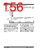
156 / 276 page  PIC16F7X7 DS30498C-page 154 2004 Microchip Technology Inc. REGISTER 12-3: ADCON2: A/D CONTROL REGISTER 2 (ADDRESS 9Bh) The analog reference voltage is software selectable to either the device’s positive and negative supply voltage (VDD and VSS) or the voltage level on the RA3/AN3/VREF+ and RA2/AN2/VREF-/CVREF pins. The A/D converter has a unique feature of being able to operate while the device is in Sleep mode. To operate in Sleep, the A/D conversion clock must be derived from the A/D’s internal RC oscillator. The output of the sample and hold is the input into the converter which generates the result via successive approximation. A device Reset forces all registers to their Reset state. This forces the A/D module to be turned off and any conversion in progress is aborted. Each port pin associated with the A/D converter can be configured as an analog input or as a digital I/O. The ADRESH and ADRESL registers contain the result of the A/D conversion. When the A/D conversion is com- plete, the result is loaded into the ADRESH/ADRESL registers, the GO/DONE bit (ADCON0 register) is cleared and A/D Interrupt Flag bit, ADIF, is set. The block diagram of the A/D module is shown in Figure 12-1. U-0 U-0 R/W-0 R/W-0 R/W-0 U-0 U-0 U-0 — — ACQT2 ACQT1 ACQT0 — — — bit 7 bit 0 bit 7-6 Unimplemented: Read as ‘0’ bit 5-3 ACQT<2:0>: A/D Acquisition Time Select bits 000 =0(1) 001 =2 TAD 010 =4 TAD 011 =6 TAD 100 =8 TAD 101 =12TAD 110 =16 TAD 111 =20 TAD Note 1: If the A/D clock source is selected as RC, a time of TCY is added before the A/D clock starts. This allows the SLEEP instruction to be executed. bit 2-0 Unimplemented: Read as ‘0’ Legend: R = Readable bit W = Writable bit U = Unimplemented bit, read as ‘0’ -n = Value at POR ‘1’ = Bit is set ‘0’ = Bit is cleared x = Bit is unknown |
|
Link URL |
| Does ALLDATASHEET help your business so far? [ DONATE ] |
About Alldatasheet | Advertisement | Contact us | Privacy Policy | Link to Datasheet | Link Exchange | Manufacturer List All Rights Reserved©Alldatasheet.com |
| Russian : Alldatasheetru.com | Korean : Alldatasheet.co.kr | Spanish : Alldatasheet.es | French : Alldatasheet.fr | Italian : Alldatasheetit.com Portuguese : Alldatasheetpt.com | Polish : Alldatasheet.pl | Vietnamese : Alldatasheet.vn Indian : Alldatasheet.in | Mexican : Alldatasheet.com.mx | British : Alldatasheet.co.uk | New Zealand : Alldatasheet.co.nz |
|
Family Site : ic2ic.com |
icmetro.com |
 New Zealand ▼
 English
 Chinese
 German
 Japanese
 Russian
 Korean
 Spanish
 French
 Italian
 Portuguese
 Polish
 Vietnamese
 Indian
 Mexican
 British
 New Zealand