|
Electronic Components Datasheet Search |
|
|
Electronic Components Datasheet Search |
|
PIC16F7X7 Datasheet(PDF) 235 Page - Microchip Technology |
|
|
|||||||||||||||||||||||||||||
PIC16F7X7 Datasheet(HTML) 235 Page - Microchip Technology |
|
|
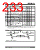
235 / 276 page  2004 Microchip Technology Inc. DS30498C-page 233 PIC16F7X7 TABLE 18-12: I2C™ BUS DATA REQUIREMENTS Param. No. Symbol Characteristic Min Max Units Conditions 100* THIGH Clock High Time 100 kHz mode 4.0 — µs Device must operate at a minimum of 1.5 MHz 400 kHz mode 0.6 — µs Device must operate at a minimum of 10 MHz SSP module 1.5 TCY — 101* TLOW Clock Low Time 100 kHz mode 4.7 — µs Device must operate at a minimum of 1.5 MHz 400 kHz mode 1.3 — µs Device must operate at a minimum of 10 MHz SSP module 1.5 TCY — 102* TR SDA and SCL Rise Time 100 kHz mode — 1000 ns 400 kHz mode 20 + 0.1 CB 300 ns CB is specified to be from 10-400 pF 103* TF SDA and SCL Fall Time 100 kHz mode — 300 ns 400 kHz mode 20 + 0.1 CB 300 ns CB is specified to be from 10-400 pF 90* TSU:STA Start Condition Setup Time 100 kHz mode 4.7 — µs Only relevant for Repeated Start condition 400 kHz mode 0.6 — µs 91* THD:STA Start Condition Hold Time 100 kHz mode 4.0 — µs After this period, the first clock pulse is generated 400 kHz mode 0.6 — µs 106* THD:DAT Data Input Hold Time 100 kHz mode 0 — ns 400 kHz mode 0 0.9 µs 107* TSU:DAT Data Input Setup Time 100 kHz mode 250 — ns (Note 2) 400 kHz mode 100 — ns 92* TSU:STO Stop Condition Setup Time 100 kHz mode 4.7 — µs 400 kHz mode 0.6 — µs 109* TAA Output Valid from Clock 100 kHz mode — 3500 ns (Note 1) 400 kHz mode — — ns 110* TBUF Bus Free Time 100 kHz mode 4.7 — µs Time the bus must be free before a new transmission can start 400 kHz mode 1.3 — µs CB Bus Capacitive Loading — 400 pF * These parameters are characterized but not tested. Note 1: As a transmitter, the device must provide this internal minimum delay time to bridge the undefined region (min. 300 ns) of the falling edge of SCL to avoid unintended generation of Start or Stop conditions. 2: A Fast mode (400 kHz) I2C™ bus device can be used in a Standard mode (100 kHz) I2C bus system but the requirement, TSU:DAT ≥ 250 ns, must then be met. This will automatically be the case if the device does not stretch the LOW period of the SCL signal. If such a device does stretch the LOW period of the SCL signal, it must output the next data bit to the SDA line, TR max. + TSU:DAT = 1000 + 250 = 1250 ns (according to the standard mode I2C bus specification), before the SCL line is released. |
|
Link URL |
| Does ALLDATASHEET help your business so far? [ DONATE ] |
About Alldatasheet | Advertisement | Contact us | Privacy Policy | Link to Datasheet | Link Exchange | Manufacturer List All Rights Reserved©Alldatasheet.com |
| Russian : Alldatasheetru.com | Korean : Alldatasheet.co.kr | Spanish : Alldatasheet.es | French : Alldatasheet.fr | Italian : Alldatasheetit.com Portuguese : Alldatasheetpt.com | Polish : Alldatasheet.pl | Vietnamese : Alldatasheet.vn Indian : Alldatasheet.in | Mexican : Alldatasheet.com.mx | British : Alldatasheet.co.uk | New Zealand : Alldatasheet.co.nz |
|
Family Site : ic2ic.com |
icmetro.com |
 New Zealand ▼
 English
 Chinese
 German
 Japanese
 Russian
 Korean
 Spanish
 French
 Italian
 Portuguese
 Polish
 Vietnamese
 Indian
 Mexican
 British
 New Zealand