|
Electronic Components Datasheet Search |
|
|
Electronic Components Datasheet Search |
|
PIC16F7X7 Datasheet(PDF) 175 Page - Microchip Technology |
|
|
|||||||||||||||||||||||||||||
PIC16F7X7 Datasheet(HTML) 175 Page - Microchip Technology |
|
|
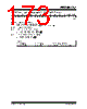
175 / 276 page  2004 Microchip Technology Inc. DS30498C-page 173 PIC16F7X7 15.3 MCLR PIC16F7X7 devices have a noise filter in the MCLR Reset path. This filter will detect and ignore small pulses. It should be noted that a WDT Reset does not drive MCLR pin low. The behavior of the ESD protection on the MCLR pin has been altered from previous devices of this family. Voltages applied to the pin that exceed its specification can result in both MCLR and excessive current, beyond the device specification, during the ESD event. For this reason, Microchip recommends that the MCLR pin no longer be tied directly to VDD. The use of an RC network, as shown in Figure 15-2, is suggested. The MCLR/VPP/RE3 pin can be configured for MCLR (default) or as an input pin (RE3). This is configured through the MCLRE bit in Configuration Word Register 1. FIGURE 15-2: RECOMMENDED MCLR CIRCUIT 15.4 Power-on Reset (POR) A Power-on Reset pulse is generated on-chip when VDD rise is detected (in the range of 1.2V-1.7V). To take advantage of the POR, tie the MCLR pin to VDD as described in Section 15.3 “MCLR”. A maximum rise time for VDD is specified. See Section 18.0 “Electrical Characteristics” for details. When the device starts normal operation (exits the Reset condition), device operating parameters (volt- age, frequency, temperature, ...) must be met to ensure operation. If these conditions are not met, the device must be held in Reset until the operating conditions are met. For more information, see Application Note AN607 “Power-up Trouble Shooting” (DS00607). 15.5 Power-up Timer (PWRT) The Power-up Timer (PWRT) of the PIC16F7X7 is a counter that uses the INTRC oscillator as the clock input. This yields a count of 72 ms. While the PWRT is counting, the device is held in Reset. The power-up time delay depends on the INTRC and will vary from chip-to-chip due to temperature and process variation. See DC parameter #33 for details. The PWRT is enabled by clearing configuration bit PWRTEN. 15.6 Oscillator Start-up Timer (OST) The Oscillator Start-up Timer (OST) provides a 1024 oscillator cycle (from OSC1 input) delay after the PWRT delay is over (if enabled). This helps to ensure that the crystal oscillator or resonator has started and stabilized. The OST time-out is invoked only for XT, LP and HS modes and only on Power-on Reset or wake-up from Sleep. 15.7 Brown-out Reset (BOR) Three configuration bits (BOREN – Configuration Word Register 1, bit 6; BORSEN – Configuration Word Register 2, bit 6; SBOREN – PCON register, bit 2) together disable or enable the Brown-out Reset circuit in one of its three operating modes. If VDD falls below VBOR (defined by BORV<1:0> bits in Configuration Word Register 1) for longer than TBOR (parameter #35, about 100 µs), the brown-out situation will reset the device. If VDD falls below VBOR for less than TBOR, a Reset may not occur. Once the brown-out occurs, the device will remain in Brown-out Reset until VDD rises above VBOR. The Power-up Timer (if enabled) will keep the device in Reset for TPWRT (parameter #33, about 72 ms). If VDD should fall below VBOR during TPWRT, the Brown-out Reset process will restart when VDD rises above VBOR with the Power-up Timer Reset. Unlike previous PIC16 devices, the PWRT is no longer automatically enabled when the Brown-out Reset circuit is enabled. The PWRTEN and BOREN configuration bits are independent of each other. C1 0.1 µF R1 1 k Ω (or greater) (optional, not critical) VDD MCLR PIC16F7X7 |
|
Link URL |
| Does ALLDATASHEET help your business so far? [ DONATE ] |
About Alldatasheet | Advertisement | Contact us | Privacy Policy | Link to Datasheet | Link Exchange | Manufacturer List All Rights Reserved©Alldatasheet.com |
| Russian : Alldatasheetru.com | Korean : Alldatasheet.co.kr | Spanish : Alldatasheet.es | French : Alldatasheet.fr | Italian : Alldatasheetit.com Portuguese : Alldatasheetpt.com | Polish : Alldatasheet.pl | Vietnamese : Alldatasheet.vn Indian : Alldatasheet.in | Mexican : Alldatasheet.com.mx | British : Alldatasheet.co.uk | New Zealand : Alldatasheet.co.nz |
|
Family Site : ic2ic.com |
icmetro.com |
 New Zealand ▼
 English
 Chinese
 German
 Japanese
 Russian
 Korean
 Spanish
 French
 Italian
 Portuguese
 Polish
 Vietnamese
 Indian
 Mexican
 British
 New Zealand