|
Electronic Components Datasheet Search |
|
|
Electronic Components Datasheet Search |
|
PIC16F7X7 Datasheet(PDF) 194 Page - Microchip Technology |
|
|
|||||||||||||||||||||||||||||
PIC16F7X7 Datasheet(HTML) 194 Page - Microchip Technology |
|
|
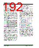
194 / 276 page  PIC16F7X7 DS30498C-page 192 2004 Microchip Technology Inc. 15.19 In-Circuit Debugger When the DEBUG bit in the Configuration Word is pro- grammed to a ‘0’, the In-Circuit Debugger functionality is enabled. This function allows simple debugging functions when used with MPLAB® ICD. When the microcontroller has this feature enabled, some of the resources are not available for general use. Table 15-7 shows which features are consumed by the background debugger. TABLE 15-7: DEBUGGER RESOURCES To use the In-Circuit Debugger function of the micro- controller, the design must implement In-Circuit Serial Programming connections to MCLR/VPP, VDD, GND, RB7 and RB6. This will interface to the In-Circuit Debugger module available from Microchip or one of the third party development tool companies. 15.20 Program Verification/Code Protection If the code protection bit(s) have not been programmed, the on-chip program memory can be read out for verification purposes. 15.21 ID Locations Four memory locations (2000h-2003h) are designated as ID locations where the user can store checksum or other code identification numbers. These locations are not accessible during normal execution but are readable and writable during program/verify. It is recommended that only the four Least Significant bits of the ID location are used. 15.22 In-Circuit Serial Programming PIC16F7X7 microcontrollers can be serially programmed while in the end application circuit. This is simply done with two lines for clock and data and three other lines for power, ground and the programming voltage (see Figure 15-17 for an example). This allows customers to manufacture boards with unprogrammed devices and then program the microcontroller just before shipping the product. This also allows the most recent firmware or a custom firmware to be programmed. For general information of serial programming, please refer to the “In-Circuit Serial Programming™ (ICSP™) Guide” (DS30277). FIGURE 15-17: TYPICAL IN-CIRCUIT SERIAL PROGRAMMING™ CONNECTION I/O pins RB6, RB7 Stack 1 level Program Memory Address 0000h must be NOP Last 100h words Data Memory 0x070 (0x0F0, 0x170, 0x1F0) 0x165-0x16F Note: In-Circuit Debugger operation must occur between the operating voltage range (VDD) of 4.75V-5.25V on PIC16F7X7 devices. External Connector Signals To Normal Connections To Normal Connections PIC16F7X7 VDD VSS MCLR/VPP/RE3 RB6 RB7 +5V 0V VPP CLK Data I/O VDD * * * * * Isolation devices (as required). |
|
Link URL |
| Does ALLDATASHEET help your business so far? [ DONATE ] |
About Alldatasheet | Advertisement | Contact us | Privacy Policy | Link to Datasheet | Link Exchange | Manufacturer List All Rights Reserved©Alldatasheet.com |
| Russian : Alldatasheetru.com | Korean : Alldatasheet.co.kr | Spanish : Alldatasheet.es | French : Alldatasheet.fr | Italian : Alldatasheetit.com Portuguese : Alldatasheetpt.com | Polish : Alldatasheet.pl | Vietnamese : Alldatasheet.vn Indian : Alldatasheet.in | Mexican : Alldatasheet.com.mx | British : Alldatasheet.co.uk | New Zealand : Alldatasheet.co.nz |
|
Family Site : ic2ic.com |
icmetro.com |
 New Zealand ▼
 English
 Chinese
 German
 Japanese
 Russian
 Korean
 Spanish
 French
 Italian
 Portuguese
 Polish
 Vietnamese
 Indian
 Mexican
 British
 New Zealand