|
Electronic Components Datasheet Search |
|
|
Electronic Components Datasheet Search |
|
PIC16F7X7 Datasheet(PDF) 193 Page - Microchip Technology |
|
|
|||||||||||||||||||||||||||||
PIC16F7X7 Datasheet(HTML) 193 Page - Microchip Technology |
|
|
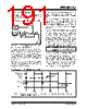
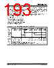
193 / 276 page  2004 Microchip Technology Inc. DS30498C-page 191 PIC16F7X7 15.18.2 WAKE-UP USING INTERRUPTS When global interrupts are disabled (GIE cleared) and any interrupt source has both its interrupt enable bit and interrupt flag bit set, one of the following will occur: • If the interrupt occurs before the execution of a SLEEP instruction, the SLEEP instruction will complete as a NOP. Therefore, the WDT and WDT prescaler and postscaler (if enabled) will not be cleared, the TO bit will not be set and the PD bit will not be cleared. • If the interrupt occurs during or after the execution of a SLEEP instruction, the device will immediately wake-up from Sleep. The SLEEP instruction will be completely executed before the wake-up. Therefore, the WDT and WDT prescaler and postscaler (if enabled) will be cleared, the TO bit will be set and the PD bit will be cleared. Even if the flag bits were checked before executing a SLEEP instruction, it may be possible for flag bits to become set before the SLEEP instruction completes. To determine whether a SLEEP instruction executed, test the PD bit. If the PD bit is set, the SLEEP instruction was executed as a NOP. To ensure that the WDT is cleared, a CLRWDT instruction should be executed before a SLEEP instruction. FIGURE 15-16: WAKE-UP FROM SLEEP THROUGH INTERRUPT Q1 Q2 Q3 Q4 Q1 Q2 Q3 Q4 Q1 Q1 Q2 Q3 Q4 Q1 Q2 Q3 Q4 Q1 Q2 Q3 Q4 Q1 Q2 Q3 Q4 OSC1 CLKO(4) INT pin INTF Flag (INTCON<1>) GIE bit (INTCON<7>) INSTRUCTION FLOW PC Instruction Fetched Instruction Executed PC PC + 1 PC + 2 Inst(PC) = Sleep Inst(PC – 1) Inst(PC + 1) Sleep Processor in Sleep Interrupt Latency (Note 2) Inst(PC + 2) Inst(PC + 1) Inst(0004h) Inst(0005h) Inst(0004h) Dummy Cycle PC + 2 0004h 0005h Dummy Cycle TOST(2) PC + 2 Note 1: XT, HS or LP Oscillator mode assumed. 2: TOST = 1024 TOSC (drawing not to scale). This delay will not be there for RC Oscillator mode. 3: GIE = 1 assumed. In this case, after wake-up, the processor jumps to the interrupt routine. If GIE = 0, execution will continue in-line. 4: CLKO is not available in these oscillator modes but shown here for timing reference. |
|
Link URL |
| Does ALLDATASHEET help your business so far? [ DONATE ] |
About Alldatasheet | Advertisement | Contact us | Privacy Policy | Link to Datasheet | Link Exchange | Manufacturer List All Rights Reserved©Alldatasheet.com |
| Russian : Alldatasheetru.com | Korean : Alldatasheet.co.kr | Spanish : Alldatasheet.es | French : Alldatasheet.fr | Italian : Alldatasheetit.com Portuguese : Alldatasheetpt.com | Polish : Alldatasheet.pl | Vietnamese : Alldatasheet.vn Indian : Alldatasheet.in | Mexican : Alldatasheet.com.mx | British : Alldatasheet.co.uk | New Zealand : Alldatasheet.co.nz |
|
Family Site : ic2ic.com |
icmetro.com |
 New Zealand ▼
 English
 Chinese
 German
 Japanese
 Russian
 Korean
 Spanish
 French
 Italian
 Portuguese
 Polish
 Vietnamese
 Indian
 Mexican
 British
 New Zealand