|
Electronic Components Datasheet Search |
|
|
Electronic Components Datasheet Search |
|
PIC16F7X7 Datasheet(PDF) 188 Page - Microchip Technology |
|
|
|||||||||||||||||||||||||||||
PIC16F7X7 Datasheet(HTML) 188 Page - Microchip Technology |
|
|
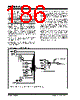
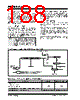
188 / 276 page 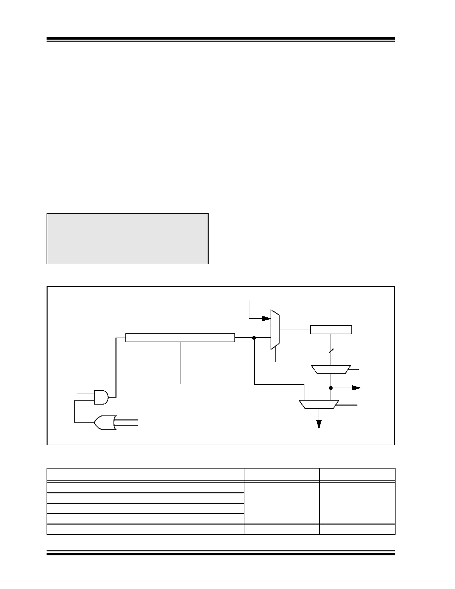 PIC16F7X7 DS30498C-page 186 2004 Microchip Technology Inc. 15.17 Watchdog Timer (WDT) For PIC16F7X7 devices, the WDT has been modified from previous PIC16 devices. The new WDT is code and functionally backward compatible with previous PIC16 WDT modules and allows the user to have a scaler value for the WDT and TMR0 at the same time. In addition, the WDT time-out value can be extended to 268 seconds, using the prescaler with the postscaler when the PSA bit is set to ‘1’. 15.17.1 WDT OSCILLATOR The WDT derives its time base from the 31.25 kHz INTRC; therefore, the accuracy of the 31.25 kHz will be the same accuracy for the WDT time-out period. The value of WDTCON is ‘---0 1000’ on all Resets. This gives a nominal time base of 16.38 ms which is compatible with the time base generated with previous PIC16 microcontroller versions. A new prescaler has been added to the path between the internal RC and the multiplexors used to select the path for the WDT. This prescaler is 16 bits and can be programmed to divide the internal RC by 32 to 65536, giving the time base used for the WDT a nominal range of 1 ms to 2.097s. 15.17.2 WDT CONTROL The WDTEN bit is located in Configuration Word Register 1 and when this bit is set, the WDT runs continuously. The SWDTEN bit is in the WDTCON register. When the WDTEN bit in the Configuration Word Register 1 is set, the SWDTEN bit has no effect. If WDTEN is clear, then the SWDTEN bit can be used to enable and disable the WDT. Setting the bit will enable it and clearing the bit will disable it. The PSA and PS<2:0> bits (OPTION_REG) have the same function as in previous versions of the PIC16 family of microcontrollers. FIGURE 15-12: WATCHDOG TIMER BLOCK DIAGRAM Note: When the OST is invoked, the WDT is held in Reset because the WDT ripple counter is used by the OST to perform the oscilla- tor delay count. When the OST count has expired, the WDT will begin counting (if enabled). TABLE 15-5: PRESCALER/POSTSCALER BIT STATUS Conditions Prescaler Postscaler (PSA = 1) WDTEN = 0 Cleared Cleared CLRWDT Command Oscillator Fail Detected Exit Sleep + System Clock = T1OSC, EXTRC, INTRC, EXTCLK Exit Sleep + System Clock = XT, HS, LP Cleared at end of OST Cleared at end of OST 31.25 kHz PSA 16-bit Programmable Prescaler WDT From TMR0 Clock Source Postscaler 8 PS<2:0> PSA WDT Time-out To TMR0 WDTPS<3:0> WDTEN from Configuration Word Register 1 1 1 0 0 SWDTEN from WDTCON Register INTRC Clock |
|
Link URL |
| Does ALLDATASHEET help your business so far? [ DONATE ] |
About Alldatasheet | Advertisement | Contact us | Privacy Policy | Link to Datasheet | Link Exchange | Manufacturer List All Rights Reserved©Alldatasheet.com |
| Russian : Alldatasheetru.com | Korean : Alldatasheet.co.kr | Spanish : Alldatasheet.es | French : Alldatasheet.fr | Italian : Alldatasheetit.com Portuguese : Alldatasheetpt.com | Polish : Alldatasheet.pl | Vietnamese : Alldatasheet.vn Indian : Alldatasheet.in | Mexican : Alldatasheet.com.mx | British : Alldatasheet.co.uk | New Zealand : Alldatasheet.co.nz |
|
Family Site : ic2ic.com |
icmetro.com |
 New Zealand ▼
 English
 Chinese
 German
 Japanese
 Russian
 Korean
 Spanish
 French
 Italian
 Portuguese
 Polish
 Vietnamese
 Indian
 Mexican
 British
 New Zealand