|
Electronic Components Datasheet Search |
|
|
Electronic Components Datasheet Search |
|
ELANSC520 Datasheet(PDF) 71 Page - Advanced Micro Devices |
|
|
|||||||||||||||||||||||||||||
ELANSC520 Datasheet(HTML) 71 Page - Advanced Micro Devices |
|
|
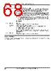
71 / 440 page  PCI Bus Host Bridge Registers Élan™SC520 Microcontroller Register Set Manual 6-7 Host Bridge Target Interrupt Status (HBTGTIRQSTA) Memory-Mapped MMCR Offset 64h Register Description This register contains the host bridge target interrupt status bits and active master identification. Bit Definitions 15 14 13 12 11 10 9 8 Bit Reserved T_IRQ_ID[3–0] Reset 00001111 R/W RSV R 7 6 5 4 3 2 1 0 Bit Reserved T_DLYTO_ IRQ_STA T_APER_ IRQ_STA T_DPER_ IRQ_STA Reset 00000000 R/W RSV R/W! R/W! R/W! Bit Name Function 15 –12 Reserved Reserved This bit field should be written to 0 for normal system operation. 11 –8 T_IRQ_ID[3–0] Target Interrupt Identification This bit field reports which PCI bus master was active when the target controller detected an error condition (delay transaction time-out, address parity error, data parity error). This bit field is only valid when an interrupt status bit is set. It is reset to 1111b when the interrupt status is cleared. 0000 = PCI bus master 0 was active when the error was detected. 0001 = PCI bus master 1 was active when the error was detected. 0010 = PCI bus master 2 was active when the error was detected. 0011 = PCI bus master 3 was active when the error was detected. 0100 = PCI bus master 4 was active when the error was detected. 1111 = No error was detected or the bus master value was not latched. For example, a bus master value is not latched if multiple interrupts are pending and one interrupt status was cleared. Other =Reserved. When multiple interrupts are pending, this bit field represents the PCI bus master active when the first interrupt occurred, but there is no way for software to detect which interrupt this is. 7 –3 Reserved Reserved This bit field should be written to 0 for normal system operation. 2T_DLYTO_ IRQ_STA Target Delayed Transaction Time-Out Interrupt Status This bit is set when the target controller issues a delayed transaction retry, the PCI bus master does not retry the transaction within 215 clocks, and the target controller is idle (i.e., no PCI-to- SDRAM transaction is active on the PCI bus). 0 = Delayed transaction time-out has not occurred. 1 = Delayed transaction time-out has occurred. This bit is cleared by writing a 1. The target controller discards the delayed transaction request when this bit is set. This bit operates regardless of the corresponding interrupt enable bit (T_DLYTO_IRQ_ENB in the HBTGTIRQCTL register, see page 6-5). |
|
Link URL |
| Does ALLDATASHEET help your business so far? [ DONATE ] |
About Alldatasheet | Advertisement | Contact us | Privacy Policy | Link to Datasheet | Link Exchange | Manufacturer List All Rights Reserved©Alldatasheet.com |
| Russian : Alldatasheetru.com | Korean : Alldatasheet.co.kr | Spanish : Alldatasheet.es | French : Alldatasheet.fr | Italian : Alldatasheetit.com Portuguese : Alldatasheetpt.com | Polish : Alldatasheet.pl | Vietnamese : Alldatasheet.vn Indian : Alldatasheet.in | Mexican : Alldatasheet.com.mx | British : Alldatasheet.co.uk | New Zealand : Alldatasheet.co.nz |
|
Family Site : ic2ic.com |
icmetro.com |
 New Zealand ▼
 English
 Chinese
 German
 Japanese
 Russian
 Korean
 Spanish
 French
 Italian
 Portuguese
 Polish
 Vietnamese
 Indian
 Mexican
 British
 New Zealand