|
Electronic Components Datasheet Search |
|
|
Electronic Components Datasheet Search |
|
ELANSC520 Datasheet(PDF) 91 Page - Advanced Micro Devices |
|
|
|||||||||||||||||||||||||||||
ELANSC520 Datasheet(HTML) 91 Page - Advanced Micro Devices |
|
|
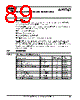
91 / 440 page  SDRAM Controller Registers Élan™SC520 Microcontroller Register Set Manual 7-3 Programming Notes SDRAM refresh cycles should only be enabled (via the RFSH_ENB bit) when the OPMODE_SEL bit is 000b. This register (DRCCTL) should be modified only when the write buffer and the read-ahead feature of the read buffer are disabled in the DBCTL register (see page 8-3). 2 –0 OPMODE_SEL [2–0] SDRAM Operation Mode Select These commands are used in the SDRAM initialization and detection algorithm. 000 = Normal SDRAM mode. 001 = NOP command enabled. 010 = CPU-to-SDRAM cycles are converted to All Banks Precharge commands. 011 = CPU-to-SDRAM cycles are converted to a Load Mode Register command. The data to be loaded is driven on MA12–MA0. 100 = Auto refresh enabled. 101–111 = Reserved. When specifying NOP, All Banks Precharge, Load Mode Register, or Auto Refresh commands, the command is not actually applied to the SDRAM devices until a CPU access to SDRAM occurs (either a read or write cycle). The specified command is issued to the SDRAM devices during the CPU access rather than the typical SDRAM read or write access. Before using a write cycle to apply any of these SDRAM commands, make sure the WB_ENB bit is clear in the DBCTL register (see page 8-3). Because the command is not issued to the SDRAM until the CPU accesses SDRAM, code executing out of ROM must specifically access SDRAM after selecting a command in the OPMODE_SEL bit field to properly configure the SDRAM device. The Load Mode Register command must be issued to the SDRAM for the setting of the CAS_LAT bit of the DRCTMCTL register to take effect (see page 7-4). In addition to setting the CAS latency as programmed in the CAS_LAT bit, the following fixed parameters are also written to the SDRAM device’s mode register when a Load Mode Register command is issued. s Burst length: always read burst 4. s Burst type: follow non-linear burst. s Operating mode: standard operation. s Write burst mode: single mode. After a command is issued, the OPMODE_SEL bit field must be cleared to 000b (normal SDRAM mode) before any further SDRAM access. |
|
Link URL |
| Does ALLDATASHEET help your business so far? [ DONATE ] |
About Alldatasheet | Advertisement | Contact us | Privacy Policy | Link to Datasheet | Link Exchange | Manufacturer List All Rights Reserved©Alldatasheet.com |
| Russian : Alldatasheetru.com | Korean : Alldatasheet.co.kr | Spanish : Alldatasheet.es | French : Alldatasheet.fr | Italian : Alldatasheetit.com Portuguese : Alldatasheetpt.com | Polish : Alldatasheet.pl | Vietnamese : Alldatasheet.vn Indian : Alldatasheet.in | Mexican : Alldatasheet.com.mx | British : Alldatasheet.co.uk | New Zealand : Alldatasheet.co.nz |
|
Family Site : ic2ic.com |
icmetro.com |
 New Zealand ▼
 English
 Chinese
 German
 Japanese
 Russian
 Korean
 Spanish
 French
 Italian
 Portuguese
 Polish
 Vietnamese
 Indian
 Mexican
 British
 New Zealand